Repair Chevrolet Repair Toyota Repair Honda Repair AvtoVAZ Repair Mercedes-Benz Repair BMW Repair Opel
Home  |  Contacts  |  Sitemap  |    
English Русский
Български
Беларускі
Український
Српски
Hrvatski
Română
Polski
Slovenský
Magyar
AudiManual.ru


  • AUDI 80
  • AUDI 100
  • AUDI A3
  • AUDI A4
  • AUDI A6
  • AUDI A8
  • AUDI Q
  • OTHER
  • ARTICLES
B8 (2007-2015) B7 (2004-2008) B6 (2000-2006) B6 (2000-2006, petrol) B5 (1994-2001) B5 (1994-2001, petrol)

Removal, installation and checking the clutch (Audi A4 B6)

  • Home
  • Audi A4
  • B6 (2000-2006)
  • Transmission
  • Clutch and drive shafts
  • Removal, installation and checking the clutch
            0
Table of contents: Removal ↓ Examination ↓ Installation ↓
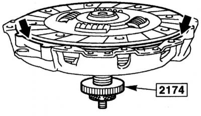
Warning: To install the clutch, you will need the AUDI-3176 centering mandrel or a standard centering tool such as the HAZET 2174.


Removal


1. Remove the gearbox, refer to Section Removal and installation of gearbox.

2. To prevent the flywheel from turning when unscrewing the mounting bolts, secure the flywheel with a screwdriver and mandrel or the AUDI-3067 tool.

2. To prevent the flywheel from turning when unscrewing the mounting bolts, secure the flywheel…


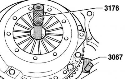
Warning: The AUDI-3067 tool is shown in the accompanying illustration in the installed position, when removing the tool, it must be turned upside down.


3. Loosen the pressure plate mounting bolts crosswise by 1 – 1.5 turns to relieve the pressure plate.

Caution: If the bolts are completely loosened immediately, the pressure springs may be damaged.


4. After loosening the bolts, unscrew them completely.

5. Remove the pressure and driven disks.

Caution: Do not drop the discs when removing them, otherwise, after installation, difficulty in disengaging the clutch and jerky operation may occur.


6. Wipe the clutch release bearing without rinsing it.

7. Wipe the flywheel.

Examination


1. Check the pressure plate for signs of overheating and grooves.


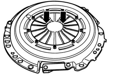
2. Check the ends of the pressure springs (arrows in the accompanying illustration). Wear up to half of their thickness is allowed.

2. Check the ends of the pressure springs (arrows in the accompanying illustration). Wear up to…


3. Check the spring connections between the pressure plate and the cover for cracks. Check the reliability of the riveted connections. If the rivets are loose, the clutch must be replaced.

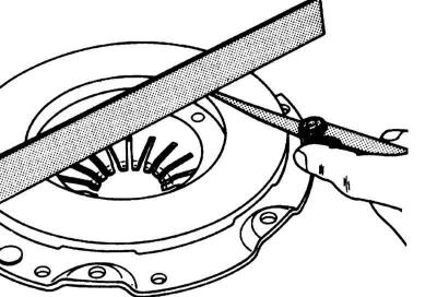
4. Check the adjacent surfaces for cracks, traces of overheating and wear. Pressure plates with an inward deflection of up to 0.2 mm can be used further. The check is carried out using a ruler and a set of feeler gauges.

4. Check the adjacent surfaces for cracks, traces of overheating and wear. Pressure plates with an…


5. Check the flywheel for signs of overheating and grooves.

6. An oily disc or a disc with mechanical damage should be replaced.

7. Check the thickness of the friction linings.


8. At the service station you can check the end runout of the disk. It should not exceed 0.8 mm (at a distance of 2.5 mm from the edge).

Caution: This check is only done on an old disc that was causing difficulty disengaging the clutch. If necessary, carefully straighten the disc.


9. Check the disc with your hand in the installed position. To do this, lightly squeeze the bearing with your hand and turn it. The bearing should rotate easily.

Caution: For clutch release bearings with a plastic ring, the ring may come off when removing the transmission or the bearing itself. This is not a reason to replace the bearing.


10. Before installing the gearbox, glue the detached ring to the bearing ring with AMW 195 KD 01 glue. In this case, the 3 noses of the plastic ring (arrows in the accompanying illustration) must enter the grooves of the bearing ring.

10. Before installing the gearbox, glue the detached ring to the bearing ring with AMW 195 KD 01…


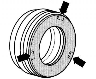
Warning: If the working surface of the plastic ring is worn more than 0.5 mm, the clutch release bearing must be replaced


11. When the car is moving, a damaged clutch release bearing will make noise when the clutch pedal is pressed. In this case, the bearing must be replaced.


Installation


Warning: Check new parts against the catalog. If used parts are installed, they must be checked beforehand.


Warning: If the old clutch disc has burned out due to overload, the pressure plate, flywheel and engine side of the gearbox must be thoroughly cleaned to eliminate the smell.


1. Before installing a new pressure plate, remove the protective anti-corrosion grease only from its working surface. Do not remove the grease from other places under any circumstances, as this may significantly reduce the service life of the clutch.

2. Check the reliability of the installation of the centering mandrel on the flywheel.

3. Clean the splines of the driven disk from rust. Lubricate the teeth of the primary shaft with a thin layer of MoS2 grease. Service stations use AUDI-G000100 grease for this. After this, move the driven disk in different directions on the primary shaft so that the hub moves easily along the shaft. Be sure to remove excess grease.

4. When installing the driven disk, make sure that the coil spring pack or the inscription "Getriebeseite" ("Gearbox side") is facing the gearbox side. The friction linings should be in contact with the flywheel. If there are color marks, make sure that the white dots of the dual mass flywheel (A) and the pressure plate (B) are opposite each other, refer to the illustration Flywheel, basket and clutch disc.

5. Center the driven disk on the pressure plate using a drift, for example, HAZET 2174 or AUDI-3176. If the driven disk is not centered, it will be impossible to insert the input shaft later.


5. Center the driven disk on the pressure plate using a drift, for example, HAZET 2174 or…


6. Install the pressure plate onto the centering pins on the flywheel.

Caution: The pressure plate must be fully seated on the flywheel. Only then insert the mounting bolts. Never tighten the pressure plate with the bolts, otherwise the centering pins and their holes may be damaged.


7. Tighten the pressure plate mounting bolts crosswise by 1–1.5 turns. Then tighten the bolts to the torque 25 Nm. In this case, the pressure plate should not be skewed, since otherwise the centering pins and their holes may be damaged.

(The original article is posted on the resource: «Audimanual.ru»)
The article was checked by auto expert Elisey Ermolaev
This article is available at russian, bulgarian, belarusian, ukrainian, serbian, croatian, romanian, polish, slovak, hungarian

Share information:
Previous articles
Audi A4 B6: Clutch and drive shafts
Next articles

General information and clutch device
Clutch and Drive Shaft Specifications
Removal and installation the bearing
Bleeding air from the clutch hydraulic system
The device of the drive shafts of the wheels
Removal and installation the drive shaft


Similar articles on other Audi car models:
Removal, installation, checking of the clutch Audi 80 B3 (1986-1991)
Clutch cable — removal and installation Audi 100 C3 (1982-1990, diesel)
Removal, installation and checking the clutch Audi A3 Type 8L (1996-2003)
Thermostat — Removal, Installation and Checking Audi A6 C5 Allroad (1999-2005)
Removal and installation the engine Audi A8 D2 (1994-2002)
Turbocharger — removal and installation Audi Q5 Type 8R (2008-2017)
Removal and installation the clutch Audi A2 (1999-2005)
Link to this page in different formats


Visitor comments

No comments yet


How much will 50 + 12 =


A4(B8, 2007-2015) 
  • General information
  • Operating instructions
  • Power unit
  • Petrol engines 1.8 l
  • Petrol engines 1.8/2.0 l
  • Petrol engines 3.0 l
  • Petrol engines 3.2 l
  • Fuel system (petrol)
  • Diesel engines 2.0 l (CA*)
  • Diesel engines 2.0 l (CJCB)
  • Diesel engines 2.7/3.0 l
  • Diesel engines 3.0 l
  • Fuel system (diesel)
  • Transmission
  • Manual gearbox 0B1
  • Manual gearbox 0B2
  • Manual gearbox 0B3
  • Manual gearbox 0B4
  • Automatic transmission 0B5
  • Automatic transmission 0B6
  • Automatic transmission 0AW
  • All-wheel drive system
  • Chassis
  • Front suspension
  • Rear suspension
  • Brake system
  • Steering system
  • Body
  • Exterior
  • Interior
  • Seats
  • Doors, locks and windows
  • Security system
  • Heating and air conditioning
  • Electrical equipment
  • Audio system
  • Power devices
  • Equipment and devices
  • Lighting and lamps
  • Electrical circuits
 
A4(B7, 2004-2008) 
  • General information
  • Introduction to manual
  • Troubleshooting
  • Operating instructions
  • Maintenance
  • Power unit
  • Petrol engines 2.0 (ALT)
  • Petrol engines 2.0 (TFSI)
  • Petrol engines 1.8 (MPI)
  • Diesel engines
  • Cooling system
  • Air conditioner
  • Fuel and exhaust system
  • Ignition system
  • Starting and charging
  • Transmission
  • Clutch
  • Manual gearbox
  • Automatic gearbox
  • Drive shafts
  • Chassis
  • Brake system
  • Front suspension
  • Rear suspension
  • Steering
  • Body
  • Exterior
  • Interior
  • Electrical equipment
  • Equipment and devices
  • Lighting and signaling
  • Windscreen wipers and washers
  • Electrical diagrams
  • Electrical diagrams (since 2007)
 
A4(B6, 2000-2006) 
  • General information
  • Vehicle Description
  • User manual
  • Maintenance
  • Power unit
  • Gasoline engine
  • Diesel engine
  • Lubrication system
  • Cooling system
  • Supply system
  • Injection system
  • Exhaust system
  • Ignition and control
  • Transmission
  • Gear box
  • Clutch and drive shafts
  • Chassis
  • Brake system
  • Car suspension
  • Steering
  • Body
  • Heating and ventilation
  • Exterior (external elements)
  • Interior (internal elements)
  • Electrical equipment
  • Power devices
  • Lighting and appliances
  • Electrical circuits
 
A4(B6, 2000-2006, petrol) 
  • General information
  • Introduction to the guide
  • Car care
  • Power unit
  • Engine repair
  • Lubrication system
  • Cooling system
  • Injection and control system
  • Ignition system
  • Power and exhaust system
  • Transmission
  • Clutch and drive shafts
  • Car gearbox
  • Chassis
  • Suspension and wheels
  • Steering
  • Brake system
  • Body
  • Interior
  • Exterior
  • Electrical equipment
  • Equipment and devices
  • Lighting and signaling
  • Power devices
  • Electrical circuits
 
A4(B5, 1994-2001) 
  • General information
  • Introduction to the guide
  • Car care
  • Maintenance (gasoline)
  • Maintenance (diesel)
  • Power unit
  • Gasoline engines
  • Diesel engines
  • Engine overhaul
  • Cooling system
  • Fuel injection (gasoline)
  • Fuel system (diesel)
  • Exhaust system
  • Ignition system
  • Transmission
  • Clutch
  • Mechanical gearbox
  • Automatic gearbox
  • Drive shafts
  • Chassis
  • Brake system
  • Car suspension
  • Steering
  • Body
  • Exterior
  • Interior
  • Doors, locks and windows
  • Heating and ventilation
  • Electrical equipment
  • Power devices
  • Equipment and devices
  • Electrical circuits
 
A4(B5, 1994-2001, petrol) 
  • General information
  • Vehicle description
  • Maintenance
  • Power unit
  • Engine repair
  • Turbocharging
  • Exhaust system
  • Cooling system
  • Ignition system
  • Fuel system
  • Motronic injection system
  • MPI and MPFI injection system
  • Transmission
  • Clutch
  • Gearbox and shafts
  • Chassis
  • Steering
  • Car suspension
  • Brake system
  • Wheels and tires
  • Body
  • Heating and ventilation
  • Body parts
  • Electrical equipment
  • Fuses and relays
  • Power devices
  • Lighting and lamps
  • Tools and devices
  • Electrical circuits
 
AudiManual.ru © 2017-2026 · Mobile version · Feedback · Sitemap: EN BG BY UA RS HR RO PL SK HU · Site search · News and articles
80 B2 · 80 B3 petrol · 80 B3 · 80 B4 · 100 C3 diesel · 100 C3 petrol · 100 C3 · 100 C4 petrol · 100 C4 · A3 Type 8L · A4 B5 petrol · A4 B5 · A4 B6 petrol · A4 B6 · A4 B7 · A4 B8 · A6 C4 · A6 C5 · A6 C5 Allroad · A8 D2 · Q5 Type 8R · Q7 Typ 4L · Audi A2 ·
This site uses cookies 🍪. Click the button to accept this fact.