



Note: The following describes the removal for a gasoline engine. Since the procedure for other engines is different, double check that all pipes and other connections from and to the cylinder head are disconnected before lifting the cylinder head. Specifics for the diesel engine are given at the end of the chapter.
The cylinder head should only be removed when the engine is cold. The intake and exhaust manifolds remain connected.
Removal
Disconnect the battery ground.
Drain the coolant and remove the air filter.
5-cylinder engine: remove the upper part of the intake manifold.
Unscrew the generator bar on the cylinder head.
Remove the coolant hose from the cylinder head and intake manifold.
Remove the low-pressure vacuum hoses from the exhaust manifold and carburetor. Mark them with tape for reinstallation.
Disconnect the gas drive, do not remove the retainer.
Disconnect the cold start actuator.
Disconnect the fuel supply line at the carburetor and plug it with a suitable plug.
Disconnect the plug connection of the intake manifold heater and the idle speed cut-off valve. Loosen the cable clamps on the cylinder head cover.
Disconnect the electrical wire and brown vacuum line from the control valve on the carburetor.
Remove the exhaust manifold muffler pipe.
Remove the upper timing belt cover.
Loosen the toothed belt and remove it from the top of the camshaft.
Mark and disconnect the electrical wire from the temperature sensor.
Disconnect the spark plug caps.
Disconnect the distributor vacuum hose on the carburetor.
Unscrew the sump on the cylinder head cover and set it aside, plugging the tubes.
Mark and remove the holder together with the cylinder head cover. Remove the oil deflector.
Unscrew the cylinder head bolts with a wrench with internal teeth (for example, HAZET 990Slg-12).
Note: Bolts must be loosened in numerical order (from 10 to 1) or from 12 to 1.
Remove the cylinder head and place it on 2 wooden blocks. Remove the cylinder head gasket.
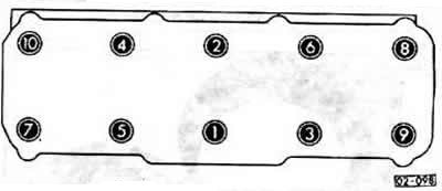
Installation
Before installing the cylinder head, clean the mating surfaces with a scraper to remove any remaining gasket material. Make sure that no dirt gets into the piston hole. Cover the holes with a cloth.
Check the mating surface of the cylinder head for flatness using a steel ruler.
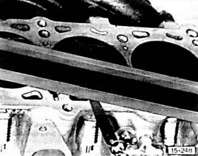
The permissible deviation from flatness is no more than 0.1 mm. Check with a feeler gauge.
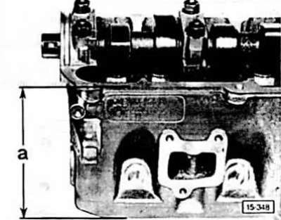
Minimum machining size for cylinder head. Minimum height 4-cylinder engine a=132.6 mm, 5-cylinder engine: 132.75 mm.
Note: The cylinder head of a diesel engine cannot be treated.
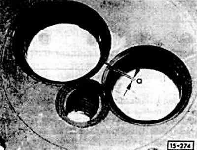
Cylinder heads with cracks between the valve seats and the first thread turns of the spark plug can be used further and can be repaired without reducing their service life if the width of the cracks does not exceed a = 0.5 mm.
Replace the cylinder head gasket.
The inscription "OBEN" (up) must face the cylinder head. Install the gaskets without sealant. For a diesel engine, ensure that the correct cylinder head gasket is used.
To center the cylinder head, use guide mandrels. To do this, cut off the heads of two old cylinder head bolts and cut slots for a screwdriver.
Screw in the guide pins (bolts with cut heads) into holes 8 and 10, for a 5-cylinder engine 9 and 10.
Turn the crankshaft so that all pistons are at the same height.
Put on the cylinder head.
The remaining 8 or 10 cylinder head bolts with washers must be screwed in by hand. The bolts must be replaced.
Remove the guide pins with a screwdriver, insert the remaining 2 bolts with washers and tighten by hand.
Caution: Cylinder head bolts must be tightened with extreme caution. Check the accuracy of the torque wrench before tightening. Bolts must be tightened on a cold engine.
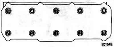
4-cylinder engine
5-cylinder engine
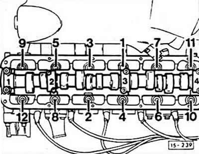
The cylinder head bolts are tightened in 3 stages. The bolts at each stage are tightened in sequence from 1 to 10 or from 1 to 12.
- step 1: Using a torque wrench, 40 Nm
- step 2: Using a torque wrench, 60 Nm
- step 3: Tighten by ½ turn (180°) with a rigid wrench. Tightening by 90° twice is acceptable.
Observe the rotation angle when tightening. Put on the key so that the handle is again along the engine. Turn ¼ turn (90°). The handle is across the engine. Another ¼ turn (90°) and the handle is again along the engine.
Caution: Tightening cylinder head bolts on a hot engine (for gasoline engine) is not allowed. On a diesel engine, tighten the bolts when the engine is warm.
Install the timing belt.
Caution: When installing the cylinder head repair kit with the camshaft installed, lubricate the contact surface between the tappet and the cam lobe.
Screw on the cylinder head cover with the oil deflector and new gaskets with a torque of 10 Nm. At the same time, screw on the sump and the carburetor ground cable.
Install the cylinder head cover of the 5-cylinder engine and install the timing belt cover.
Install the generator bar. Tighten the V-belt.
Install the exhaust pipe onto the exhaust manifold.
Connect the intake manifold heater and idle air cut-off valve electrical wires. Tighten the cable clamp on the cylinder head cover. Connect the electrical wire and brown pipe to the control valve.
Attach the vacuum hoses to the intake manifold and carburetor as marked. If necessary, tighten the hoses with screw clamps.
Connect the gas drive.
Connect and adjust the cold start actuator.
Connect the fuel supply line to the carburetor and tighten the clamp.
Place the distributor vacuum hose onto the carburetor.
Connect all ignition system hoses and tighten clamps. Fill with new coolant.
Connect the wire to the temperature sensor. Put on the spark plug tips.
5-cylinder engine: Install the upper part of the intake manifold.
Install the air filter.
Check the engine oil level. If the cylinder head gasket was faulty, change the oil.
Connect the battery ground cable.
When the engine is warm, check the coolant level. Check the tightness of the hoses and connections of the cooling system.
Check the ignition timing.
Check idle speed adjustment.
Diesel engine
Removal
Disconnect the electrical wires from the fuel shut-off valve and glow plugs.
Clean and unscrew the inlet pipes on the pump and injectors. Plug the holes with the appropriate plugs.
Remove the glow plugs and injectors.
Installation
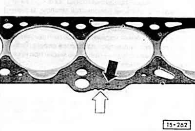
Depending on the piston size, cylinder head gaskets of different thicknesses are installed.
When replacing, observe the designation of the gaskets and install a new gasket only with the same designation. Black arrow = part number, white arrow = notches.
Tighten the cylinder head bolts with the engine warmed up. To do this, warm up the engine and let it idle until the radiator fan turns on. (Oil temperature above 50°C). Tighten the bolts an additional ¼ turn (90°) with a rigid wrench, without first loosening or removing the wrench. Observe the tightening sequence.
Install glow plugs.
Install the injectors.
Clean the high-pressure fuel line connection and tighten the union nut to 25 Nm.
Connect the electrical wires to the fuel shut-off valve and glow plugs.
Check the start of the high pressure fuel pump.
Only for 1.6 l engine: About 1000 km after repair, the cylinder head bolts should be tightened. To do this, tighten the bolts by ¼ turn (90°) with a rigid wrench, without first loosening or removing the wrench. Observe the tightening sequence. The bolts can be tightened on a cold or warm engine.
[Text provided by the online resource AUDImanual.ru]