Repair Chevrolet Repair Toyota Repair Honda Repair AvtoVAZ Repair Mercedes-Benz Repair BMW Repair Opel
Home  |  Contacts  |  Sitemap  |    
English Русский
Български
Беларускі
Український
Српски
Hrvatski
Română
Polski
Slovenský
Magyar
AudiManual.ru


  • AUDI 80
  • AUDI 100
  • AUDI A3
  • AUDI A4
  • AUDI A6
  • AUDI A8
  • AUDI Q
  • OTHER
  • ARTICLES
B4 (1991-1996) B3 (1986-1991) B3 (1986-1991, petrol) B2 (1979-1986)

Anti-lock braking system (ABS) parts — removal and installation (Audi 80 B3)

  • Home
  • Audi 80
  • B3 (1986-1991, petrol)
  • Chassis
  • Brake system
  • Anti-lock braking system (ABS) parts — removal and installation
            0
Table of contents: Hydraulic modulator ↓ Electronic control device ↓ Relay ↓ Wheel speed sensors ↓ Wheel speed sensor rotors ↓
Note: After performing any of the procedures described in this chapter, it is recommended that you have the anti-lock brake system completely checked by your Audi dealer.


Note: After performing any of the procedures described in this chapter, it is recommended that you…


Hydraulic modulator


1. Disconnect the negative battery cable.

2. Where equipped, remove the coolant expansion tank as described in Section 2, and move it to the side.

3. Accurately mark the location of each brake line on the hydraulic modulator.

4. Unscrew the cap of the additional brake system reservoir. Cover it with a piece of polyethylene to reduce fluid loss. Alternatively, the fluid can be pumped out of the reservoir into a container.

5. Loosen the union nuts, disconnect the brake lines. Seal the ends of the tubes or cover them with adhesive tape to prevent dust and dirt from entering.

6. Lift the cover off the modulator, disconnect the harness retainer and wiring.

7. Unscrew the mounting nuts and remove the modulator from the suspension.

8. Installation is carried out in the reverse order. Bleed the entire hydraulic system as described in Chapter 17.


Electronic control device


Electronic control device


9. It is located under the left rear seat cushion.

10. Check that the ignition is off.

11. Remove the seat cushion (Section 11).

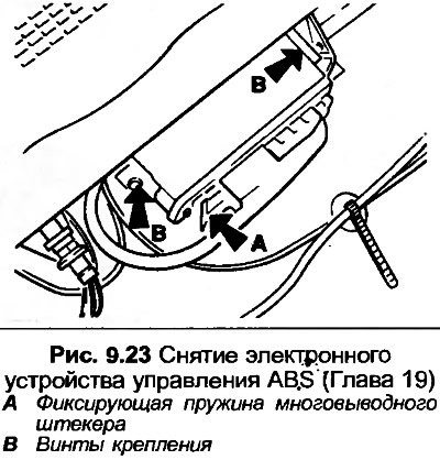
12. Press the locking spring, disconnect the multi-pin plug of the electrical wiring.

13. Unscrew both mounting screws and remove the electronic control device.

14. Installation is carried out in the reverse order, but make sure that the locking spring is fully inserted to secure the multi-pin plug.

Relay


15. There are two relays on the hydraulic modulator, one for the solenoid valve and one for the return pump. There is also a combination relay located in the auxiliary relay box under the instrument panel.

16. Turn off the ignition before removing the relay.

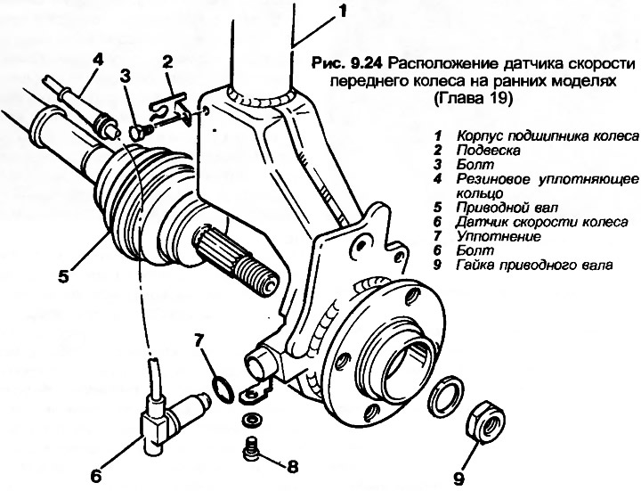
17. First remove the cover, then remove the relay from the socket.

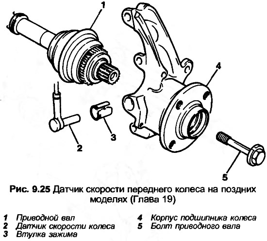
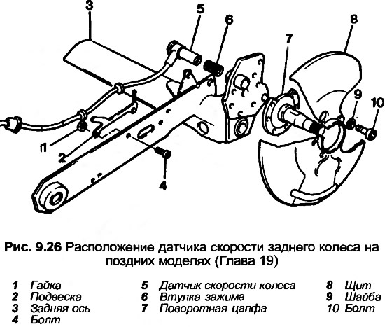
18. To remove the relay from the auxiliary relay block, follow the instructions Section 12.

19. Installation is carried out in reverse order.

Wheel speed sensors


Wheel speed sensors


Wheel speed sensors


20. Jack up the front or rear of the car and support it on axle stands. Remove the wheel.


21. On early models, the sensor is attached with a bolt. If the sensor is to be reused, mark the exact position of the bolt in the elongated hole with a dab of paint. Remove the bolt, remove the sensor from the bushing in the wheel bearing housing or rear axle. Remove the seal.

22. On later models, the sensor is attached by a clamp sleeve. Pull the sensor out, then remove the clamp sleeve from the wheel bearing housing or rear axle.

23. Release the sensor wiring from the suspension by pulling on the rubber sealing ring.

24. Disconnect the wiring harness connector located in the engine compartment or under the rear seat cushion. On fuel injected models, first disconnect the air duct from the air flow meter and move it to the side.

25. Before installing the rear sensor, check and, if necessary, adjust the rear wheel bearing clearance as described in Section 10.

26. To install the sensor on early models, it is recommended to install a new PVC tip on the sensor. However, if the sensor is to be installed exactly in the marked position, this is not necessary. Install a new seal, coat the seal and sensor with paste. Insert the sensor, tighten the bolt, pressing on the sensor so that the PVC tip touches the rotor.

27. When installing the sensor on later models, first coat the clamp sleeve with paste and insert it completely into the wheel bearing housing or rear axle. Push the sensor completely into the clamp sleeve. Install the rubber boot on the rear sensor (if any).

28. Connect the electrical wiring and, where equipped, the air duct.


29. Insert the rubber sealing ring into the hanger to secure the wiring.

30. Install the wheel and lower the car to the ground.

Wheel speed sensor rotors


31. The front sensor rotors are incorporated into the outer drive shaft joints. The joints can be replaced separately as described in Section 8.

32. Before removing the rear sensor rotor, first remove the hub as described in Section 10.

33. Clamp the hub in a vice and use a punch to knock out the rotor through the holes for the wheel bolt.

34. To install the rotor on the hub, it is necessary to use a metal pipe, being careful not to damage the special sensor.

35. Install the hub as described in Section 10.

[The original article is available on the website «AUDImanual»]
The article was checked by auto expert Timur Bazhenov
This article is available at russian, bulgarian, belarusian, ukrainian, serbian, croatian, romanian, polish, slovak, hungarian

Share information:
Previous articles
Audi 80 B3: Brake system
Next articles

Anti-lock braking system (ABS) — general description
Hydraulic system — bleeding
Brake system tubes and hoses — removal and installation
Brake pressure regulator — checking and adjustment
Anti-lock braking system (ABS) — pressure check
Brake pedal — removal and installation
Handbrake lever — removal and installation
Handbrake — adjustment


Similar articles on other Audi car models:
Anti-lock braking system indicator Audi 100 C4 (1990-1994, petrol)
Removal and installation the trunk lid lock trim Audi A3 Type 8L (1996-2003)
Removal and installation of parts and units of the lubrication… Audi A4 B7 (2004-2008)
General description of the anti-lock braking system (ABS) Audi A6 C4 (1994-1997)
Anti-lock braking system (ABS) Audi A8 D2 (1994-2002)
Removal and installation parts of the washer fluid supply system Audi Q7 Typ 4L (2005-2015, diesel)
Removal and installation the cooling system pump Audi A2 (1999-2005)
Link to this page in different formats


Visitor comments

No comments yet


How much will 39 + 34 =


80(B4, 1991-1996) 
  • General information
  • User manual
  • Maintenance
  • Troubleshooting
  • Power unit
  • Engine
  • Cooling system
  • Heating and ventilation
  • Petrol injection
  • Diesel fuel system
  • Fuel system
  • Exhaust systems
  • Ignition system
  • Transmission
  • Clutch
  • Car gearbox
  • Chassis
  • Brake system
  • Suspension and steering wheel
  • Body
  • Body and trim
  • Electrical equipment
  • Electrical system
  • Electrical circuits
 
80(B3, 1986-1991) 
  • General information
  • Repair characteristics
  • Maintenance
  • Power unit
  • Gasoline engine
  • Diesel engine
  • Engine lubrication system
  • Fuel system (gasoline)
  • Injection system (gasoline)
  • Fuel system (diesel)
  • Ignition system
  • Cooling system
  • Heater
  • Exhaust system
  • Transmission
  • Clutch and gearbox
  • Chassis
  • Steering
  • Brake system
  • Car suspension
  • Body
  • Body elements
  • Electrical equipment
  • Power devices
  • Lighting and appliances
  • Electrical circuits
 
80(B3, 1986-1991, petrol) 
  • General information
  • User manual
  • Maintenance
  • Power unit
  • Engine 4-cylinder
  • Engine 5-cylinder
  • Cooling system
  • Fuel and exhaust systems
  • Ignition system
  • Transmission
  • Clutch
  • Mechanical transmission
  • Automatic transmission
  • Drive shafts
  • Chassis
  • Brake system
  • Suspension
  • Steering
  • Body
  • Exterior
  • Interior
  • Electrical equipment
  • Equipment and devices
  • Electrical circuits
 
80(B2, 1979-1986) 
  • General information
  • User manual
  • Power unit
  • Engine FZ
  • Engine EP, YP, YZ, DT, DS, DZ
  • Transmission
  • Clutch
  • 4 speed gearbox
  • 5 speed gearbox
  • Front wheel drive
  • Chassis
  • Front suspension
  • Rear suspension
  • Steering
  • Brake system
  • Electrical equipment
  • Equipment and devices
  • Electrical circuits
 
AudiManual.ru © 2017-2026 · Mobile version · Feedback · Sitemap: EN BG BY UA RS HR RO PL SK HU · Site search · News and articles
80 B2 · 80 B3 petrol · 80 B3 · 80 B4 · 100 C3 diesel · 100 C3 petrol · 100 C3 · 100 C4 petrol · 100 C4 · A3 Type 8L · A4 B5 petrol · A4 B5 · A4 B6 petrol · A4 B6 · A4 B7 · A4 B8 · A6 C4 · A6 C5 · A6 C5 Allroad · A8 D2 · Q5 Type 8R · Q7 Typ 4L · Audi A2 ·
This site uses cookies 🍪. Click the button to accept this fact.