
Instrument cluster. Engine cooling fan
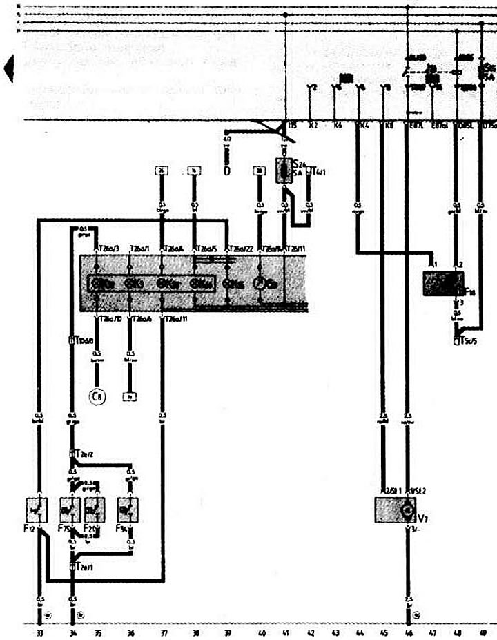
- D — ignition switch
- F12 — Starting injector control lamp switch
- F18 — sensor for switching on the electric motor of the cooling system fan
- F21 — brake booster emergency pressure warning lamp switch
- F34 — Brake fluid level indicator lamp switch
- F75 — brake booster fluid emergency level indicator switch
- G3 - coolant temperature gauge
- J26 — relay for switching on the electric motor of the cooling system fan
- KZ - oil pressure indicator lamp
- K15 - control lamp of starting injector
- K28 - emergency overheating and coolant level indicator lamp
- K32 - Brake lining wear warning lamp (PADS)
- K66 - warning lamp for malfunction of fully electronic ignition system
- S26 - fuse in additional fuse box
- T2e - 2-plug connector (in the powertrain division, on the left)
- T4 - 4-pin connector (black, behind the instrument cluster)
- T5c - 5-pin connector (yellow, behind the instrument cluster)
- T10d - 10-pin connector (yellow, behind the instrument cluster)
- T26 - 26-pin connector (black color) instrument clusters
- T26a - 26-pin connector (brown color) instrument clusters
- V7 — electric motor of the cooling system fan
- (82) - ground connection "-1-" of the left front wire harness
- (83) - ground connection "-1-" of the right front wire harness
- (C8) - brake pad wear sensor connector in the left front wiring harness
(The original article is available on the website «AudiManual.ru»)