
Diagram 1-14. Instrument cluster, engine oil level sensor, engine oil pressure warning light
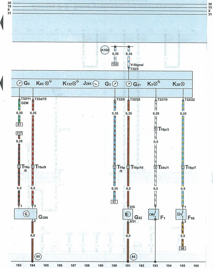
| F1 | engine oil pressure sensor |
| F66 | coolant level sensor |
| G3 | coolant temperature gauge |
| G5 | tachometer |
| G21 | speedometer |
| G22 | speedometer sensor (on the gearbox) |
| G266 | engine oil level sensor, oil change intervals |
| J285 | microprocessor on the instrument panel |
| KZ | engine oil pressure warning light |
| K28 | coolant temperature/level warning light |
| K83 | engine self-diagnosis/CO content warning light |
| K132 | electronic accelerator malfunction indicator light |
| T2dc | 2-pin black plug near cylinder #4 injector |
| T10o | 10-pin brown connector on fuse/relay box under cowl |
| T10p | 10-pin black connector on fuse/relay box under fairing |
| T32 | 32-pin blue plug on the instrument panel |
| T32a | 32-pin green plug on the instrument panel |
| 85 | connection 1 to ground (-) in the engine compartment wiring harness |
| A108 | speedometer sensor signal transmission wire in instrument cluster wiring harness |
[This article was copied from an online resource «Audimanual.ru»]