
Scheme 1-13. Instrument cluster, fuel pump
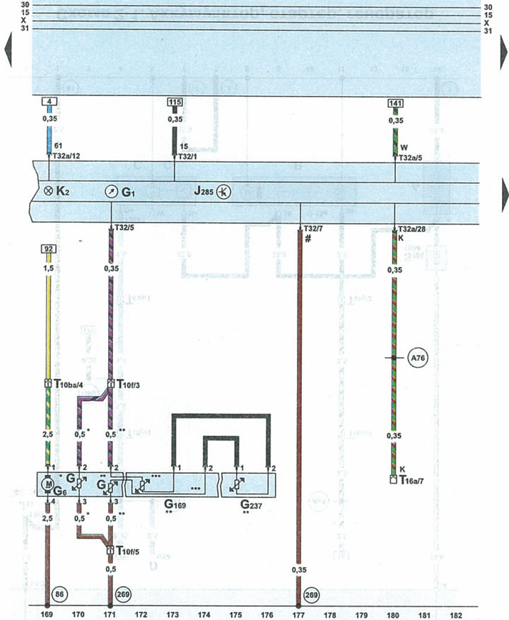
| G | fuel gauge sensor |
| G1 | fuel gauge |
| G6 | fuel pump |
| G169 | fuel gauge sensor 2 |
| G237 | fuel gauge sensor 3 |
| J285 | instrument cluster microprocessor |
| K2 | battery charging indicator light |
| T10f | 10-pin brown plug on the left side of the front pillar |
| T10ba | 10-pin blue plug on the left side of the A-pillar |
| T16a | 16-pin diagnostic connector plug |
| T32 | 32-pin blue plug on the instrument panel |
| T32a | 32-pin green plug on the instrument panel |
| 86 | wire 1 "ground" (-) in the wiring harness of the rear part of the engine compartment |
| 269 | connection of 1 sensor to "ground" in the instrument panel wiring harness |
| A76 | wire K of the diagnostic connector in the instrument panel wiring harness |
| * | front wheel drive vehicles |
| ** | all wheel drive vehicles |
| *** | wire in fuel tank |
| # | sensor contact with "ground" (-) |
The original article is available on the website: AudiManual.ru