
Diagram 1-9. Engine control unit, solenoid valve for evaporative canister purge, ABS modulator pump relay fuse
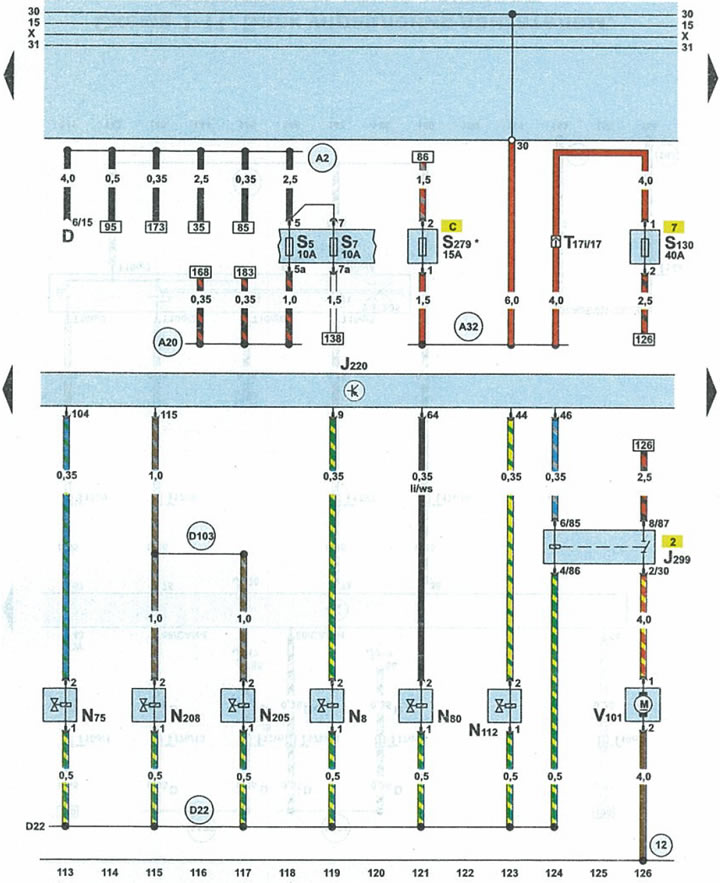
| D | ignition switch |
| J220 | engine control unit |
| J299 | afterburner pump relay |
| N8 | relief valve |
| N75 | boost air pressure reducing valve |
| N80 | evaporative Canister Purge Solenoid Valve |
| N112 | afterburner air supply valve |
| N₂05 | camshaft position adjuster valve 1 |
| N₂08 | camshaft position adjuster valve 2 |
| S5 | fuse |
| S7 | fuse |
| S130 | air pump fuse for afterburner system |
| S279 | ABS modulator pump relay fuse |
| T17i | 17-pin white plug on fuse/relay box under fairing |
| V101 | electric motor of the air pump of the afterburning system |
| 12 | ground point (-) in the engine compartment on the left side |
| A2 | positive potential wire terminal 15 in the instrument panel wiring harness |
| A20 | terminal wire 15a in the instrument panel wiring harness |
| A32 | positive potential wire terminal 30 in the instrument panel wiring harness |
| D22 | connecting the wires through fuse 34 in the wiring harness on the right side of the engine compartment |
| D103 | connection 3 in the engine compartment wiring harness |
| * | only cars with automatic transmission |
(This article was copied from an online resource: «AudiManual»)