
Diagram 1-8. Engine control unit, mass air flow sensor
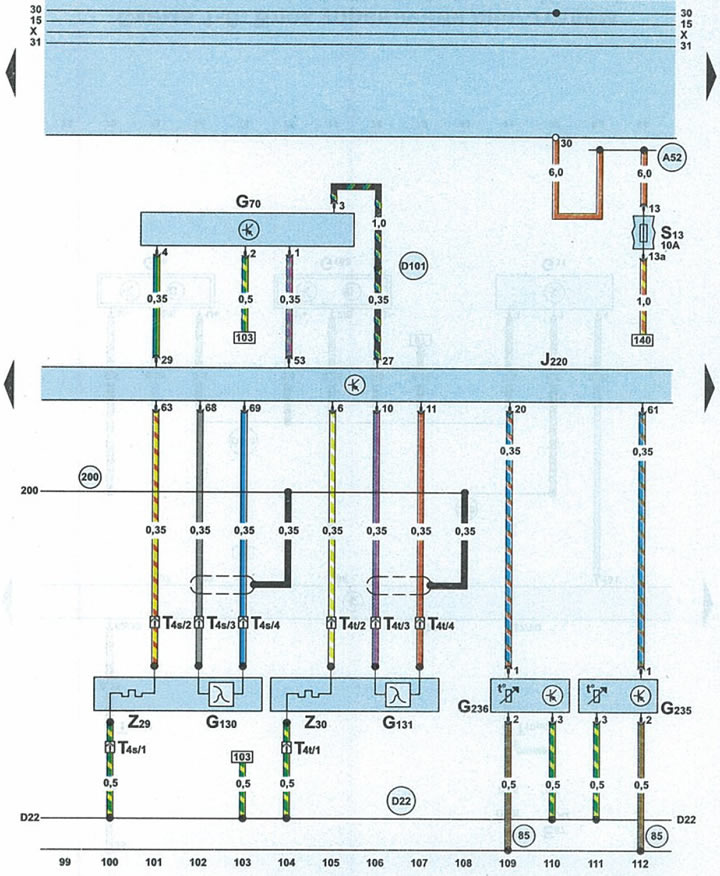
| G70 | mass air flow sensor |
| G130 | main lambda probe 1 (after catalyst) |
| G131 | main lambda probe 2 (after catalyst) |
| G235 | sensor 1 exhaust gas temperature |
| G236 | sensor 2 exhaust gas temperature |
| J220 | engine control unit |
| S13 | fuse |
| T4s | 4-pin green plug main lambda probe 1 |
| T4t | 4-pin brown plug main lambda probe 2 |
| Z29 | main lambda probe heater 1 |
| Z30 | main lambda probe heater 2 |
| 85 | connection 1 to ground (-) in the engine compartment wiring harness |
| 200 | connection to ground (-) (shielding) in the engine compartment wiring harness |
| A52 | connection 2 positive potential (terminal 30) in the instrument panel wiring harness |
| D22 | connecting the wires through fuse 34 in the wiring harness on the right side of the engine compartment |
| D101 | connection 1 in the engine compartment wiring harness |