Repair Chevrolet Repair Toyota Repair Honda Repair AvtoVAZ Repair Mercedes-Benz Repair BMW Repair Opel
Home  |  Contacts  |  Sitemap  |    
English Русский
Български
Беларускі
Український
Српски
Hrvatski
Română
Polski
Slovenský
Magyar
AudiManual.ru


  • AUDI 80
  • AUDI 100
  • AUDI A3
  • AUDI A4
  • AUDI A6
  • AUDI A8
  • AUDI Q
  • OTHER
  • ARTICLES
C5 Allroad (1999-2005) C5 (1997-2004) C4 (1994-1997)

Diagram 1-10. Engine control unit, brake light switch, throttle valve... (Audi A6 C5)

  • Home
  • Audi A6
  • C5 Allroad (1999-2005)
  • Electrical equipment
  • Schemes (petrol engine 2.7 l)
  • Diagram 1-10. Engine control unit, brake light switch, throttle valve...
            0

Schematic 1-10. Engine control unit, brake light switch, throttle valve, cruise control switch sensor on the brake pedal, clutch pedal sensor
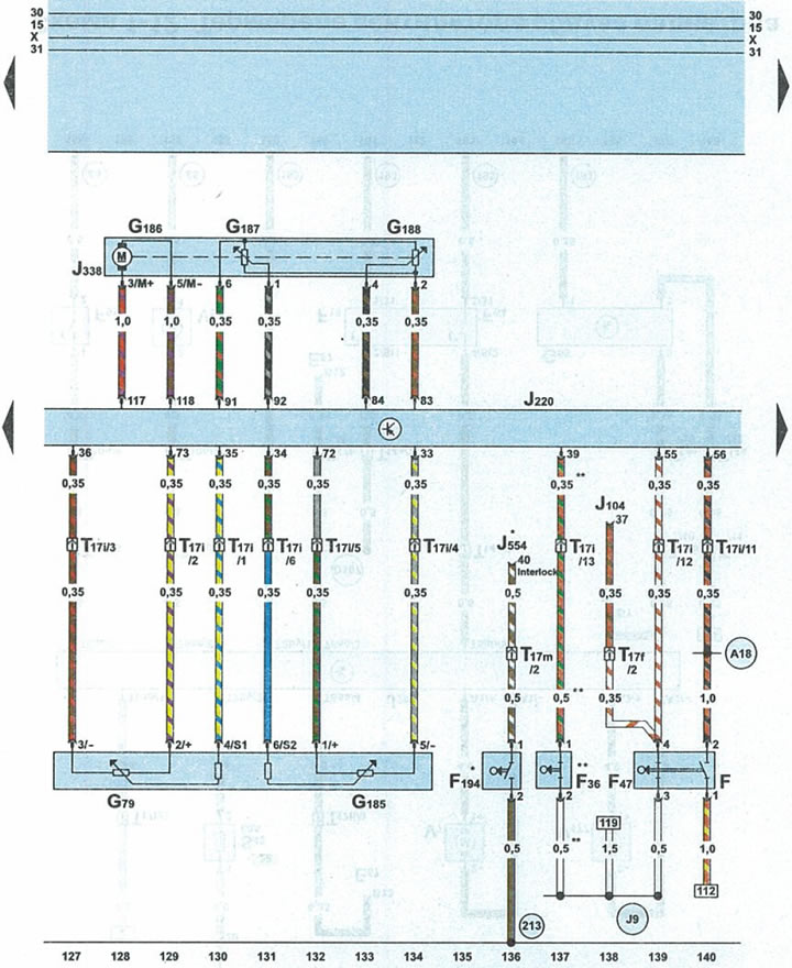


Schematic 1-10. Engine control unit, brake light switch, throttle valve, cruise control switch…


Fbrake light switch
F36clutch pedal sensor
F47cruise control switch sensor
F194clutch pedal sensor
G79accelerator pedal position sensor 1
G185accelerator pedal position sensor 2
G186sensor 1 throttle actuator (electronic accelerator)
G187throttle position sensor 1 (electronic accelerator)
G188throttle position sensor 2 (electronic accelerator)
J104ABS control unit with EDS
J220engine control unit
J338throttle valve
J554gearbox control unit with reducer
T17f17-pin black plug on relay box under glove compartment on driver's side
T17i17-pin white plug on fuse/relay box under cowl
T17m17-pin blue connector on the right side of the A-pillar
213wire 4 "ground" (-) in the instrument panel wiring harness
A18terminal 54 wire in instrument panel wiring harness
J9wire 1 terminal 15a in ABS wiring harness
*cars with gearbox 01E with reducer
**cars with manual transmission


This article was copied from the website audimanual.ru
The article was checked by auto expert Alexey Ivanov
This article is available at russian, bulgarian, belarusian, ukrainian, serbian, croatian, romanian, polish, slovak, hungarian

Share information:
Previous articles
Audi A6 C5 Allroad: Schemes (petrol engine 2.7 l)
Next articles

Scheme 1-9. Engine control unit, electromagnetic valve of purge…
Diagram 1-8. Engine control unit, mass air flow sensor
Scheme 1-7. Engine control unit, fuel pump relay, lambda probes…
Scheme 1-6. Engine control unit and inductive sensors (Hall…
Schematic 1-11. Engine control unit, cruise control switch
Diagram 1-12. Radiator fan thermal relay
Scheme 1-13. Instrument cluster, fuel pump
Diagram 1-14. Instrument cluster, engine oil level sensor...


Similar articles on other Audi car models:
Electrical diagram of the control unit of the fuel system of the… Audi 80 B4 (1991-1996)
Multipoint injection control unit, knock sensors, throttle… Audi 100 C4 (1990-1994, petrol)
Control unit for Simos, throttle control unit, power steering… Audi A3 Type 8L (1996-2003)
Brake light switch; Central control unit for comfort systems Audi A4 B8 (2007-2015)
High-mounted brake light Audi A8 D2 (1994-2002)
Brake light switch, engine control unit Audi Q5 Type 8R (2008-2017)
Engine Control Unit — Check Audi A2 (1999-2005)
Link to this page in different formats


Visitor comments

No comments yet


How much will 37 + 18 =


A6(C5 AR, 1999-2005) 
  • General information
  • User manual
  • Maintenance
  • Troubleshooting
  • Power unit
  • V6 petrol engines
  • V8 petrol engines
  • Diesel engines
  • Cooling and heating system
  • Injection system (gasoline)
  • Fuel system (diesel)
  • Supply system
  • Exhaust system
  • Ignition system
  • Transmission
  • Clutch
  • Mechanical gearbox
  • Automatic gearbox
  • Chassis
  • Brake system
  • Car suspension
  • Steering
  • Body
  • Body elements
  • Doors, locks and windows
  • Electrical equipment
  • Equipment and devices
  • Power devices
  • Electrical circuits
  • Schemes (petrol engine 2.7 l)
  • Schemes (petrol engine 4.2 l)
  • Schemes (diesel engine 2.5 l)
 
A6(C5, 1997-2004) 
  • General information
  • User manual
  • Maintenance
  • Power unit
  • Engine repair
  • Cooling system
  • Fuel system
  • Engine management
  • Fuel system (diesel)
  • Exhaust system
  • Transmission
  • Clutch
  • Car gearbox
  • Chassis
  • Front suspension
  • Rear suspension
  • Steering
  • Wheels and tires
  • Brake system
  • Body
  • Exterior
  • Interior
  • Electrical equipment
  • Air conditioner
  • Equipment and devices
  • Electrical circuits
 
A6(C4, 1994-1997) 
  • General information
  • User manual
  • Maintenance (gasoline)
  • Maintenance (Diesel)
  • Gasoline engines
  • 4 cylinder engines
  • 5 cylinder engines
  • 6 cylinder engines
  • Diesel engines
  • 4 cylinder engines
  • 5 cylinder engines
  • Engine repair
  • Removal and reassembly
  • Cooling system
  • Single point injection system
  • Multipoint injection system
  • MPI/MPFI injection system
  • Fuel system (diesel)
  • Exhaust system
  • Ignition system
  • Transmission
  • Clutch
  • Manual transmission
  • Automatic transmission
  • Drive shafts
  • Chassis
  • Brake system
  • Front suspension
  • Rear suspension
  • Steering
  • Body
  • Exterior (external elements)
  • Interior (internal elements)
  • Electrical equipment
  • Power devices
  • Lighting and appliances
  • Electrical circuits
 
AudiManual.ru © 2017-2026 · Mobile version · Feedback · Sitemap: EN BG BY UA RS HR RO PL SK HU · Site search · News and articles
80 B2 · 80 B3 petrol · 80 B3 · 80 B4 · 100 C3 diesel · 100 C3 petrol · 100 C3 · 100 C4 petrol · 100 C4 · A3 Type 8L · A4 B5 petrol · A4 B5 · A4 B6 petrol · A4 B6 · A4 B7 · A4 B8 · A6 C4 · A6 C5 · A6 C5 Allroad · A8 D2 · Q5 Type 8R · Q7 Typ 4L · Audi A2 ·
This site uses cookies 🍪. Click the button to accept this fact.