
Schematic 1-11. Engine control unit, cruise control switch
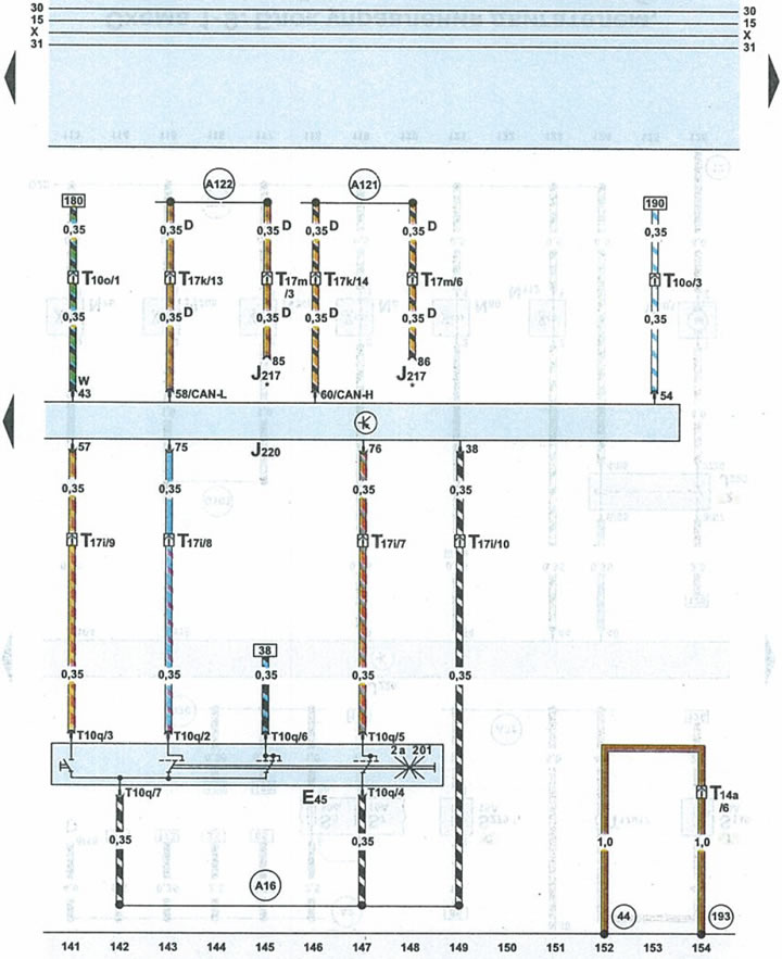
| E45 | cruise control switch |
| J217 | automatic transmission control unit |
| J220 | engine control unit |
| T10o | 10-pin brown connector on fuse/relay box under cowl |
| T1Oq | 10-pin black plug for cruise control switch |
| T14a | 14-pin black plug on the left side of the engine compartment |
| T17i | 17-pin white plug on fuse/relay box under cowl |
| T17k | 17-pin red connector on the fuse/relay box under the fairing |
| T17m | 17-pin blue connector on the right side of the A-pillar |
| 44 | ground point (-) on the left side of the front pillar below |
| 193 | wire 1 "ground" (-) in the radiator fan wiring harness |
| A16 | cruise control wire in instrument cluster wiring harness |
| A121 | high-Bus data exchange wire in the instrument panel wiring harness |
| A122 | low-Bus data exchange wire in the instrument panel wiring harness |
| D | data exchange buses |
| * | cars with automatic transmission |
(The original version is on the portal: audimanual)