Repair Chevrolet Repair Toyota Repair Honda Repair AvtoVAZ Repair Mercedes-Benz Repair BMW Repair Opel
Home  |  Contacts  |  Sitemap  |    
English Русский
Български
Беларускі
Український
Српски
Hrvatski
Română
Polski
Slovenský
Magyar
AudiManual.ru


  • AUDI 80
  • AUDI 100
  • AUDI A3
  • AUDI A4
  • AUDI A6
  • AUDI A8
  • AUDI Q
  • OTHER
  • ARTICLES
C5 Allroad (1999-2005) C5 (1997-2004) C4 (1994-1997)

Scheme 1-7. Engine control unit, fuel pump relay, lambda probes 1 and 2... (Audi A6 C5)

  • Home
  • Audi A6
  • C5 Allroad (1999-2005)
  • Electrical equipment
  • Schemes (petrol engine 2.7 l)
  • Scheme 1-7. Engine control unit, fuel pump relay, lambda probes 1 and 2...
            0

Scheme 1-7. Engine control unit, fuel pump relay, preliminary lambda probes 1 and 2, brake booster relay, brake vacuum pump
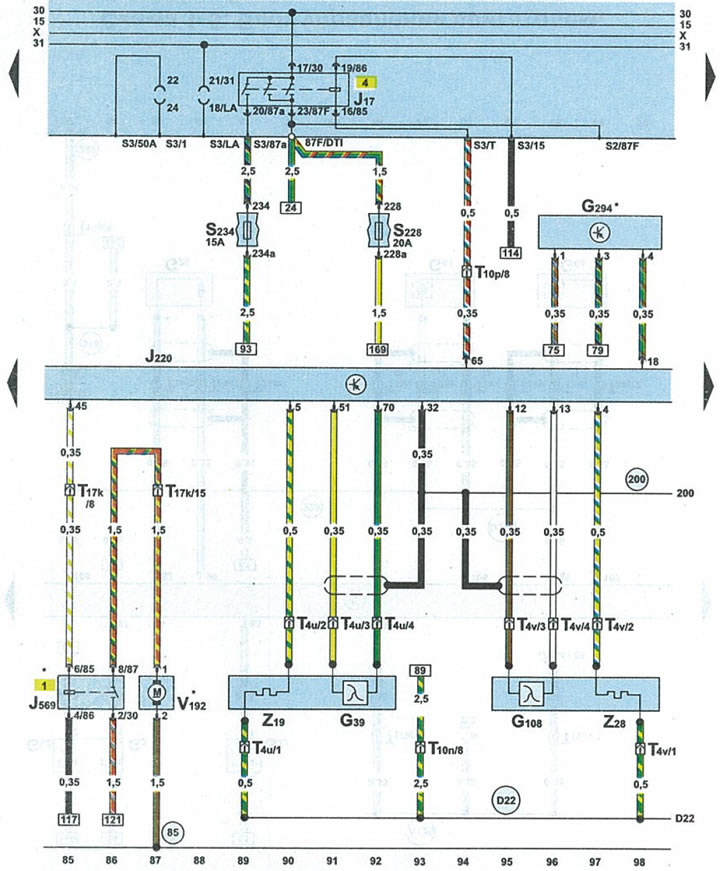


Scheme 1-7. Engine control unit, fuel pump relay, preliminary lambda probes 1 and 2, brake booster…


G39lambda probe 1
G39lambda probe 2
G294brake booster pressure sensor
J17fuel pump relay
3220engine control unit
J569brake booster relay
3228fuse 28
S234fuse 34
T4u4-pin black plug lambda probe 1
T4v4-pin black plug lambda probe 2
T10p10-pin black plug for under cowl fuse/relay box
T17k17-pin red connector for under cowl fuse/relay box
V192brake drive vacuum pump
Z19lambda probe heater 1
Z28lambda probe heater 2
85connection 1 to ground (-) in the engine compartment wiring harness
200connection to ground (-) (shielding) in the engine compartment wiring harness
D22connecting the wires through fuse 34 in the wiring harness on the right side of the engine compartment
The article was checked by auto expert Alexey Ivanov
This article is available at russian, bulgarian, belarusian, ukrainian, serbian, croatian, romanian, polish, slovak, hungarian

Share information:
Previous articles
Audi A6 C5 Allroad: Schemes (petrol engine 2.7 l)
Next articles

Scheme 1-6. Engine control unit and inductive sensors (Hall…
Scheme 1-5. Engine control unit, knock sensor 1...
Scheme 1-4. Engine control unit, ignition coils, output stage…
Scheme 1-3. Engine control unit, ignition coils, output stage…
Diagram 1-8. Engine control unit, mass air flow sensor
Scheme 1-9. Engine control unit, electromagnetic valve of purge…
Diagram 1-10. Engine control unit, brake light switch, throttle…
Schematic 1-11. Engine control unit, cruise control switch


Similar articles on other Audi car models:
Electrical diagram of the fuel pump, fuel injection system,… Audi 80 B4 (1991-1996)
Mono-Motronic injection system control unit, fuel pump relay,… Audi 100 C4 (1990-1994, petrol)
Control unit for Motronic, fuel pump relay, injectors... Audi A3 Type 8L (1996-2003)
Air flow meter, engine control unit and lambda probe — removal… Audi A4 B8 (2007-2015)
Draining water from the fuel filter of a V6 TDI diesel engine Audi A8 D2 (1994-2002)
Fuel level sensor, fuel lift pump, instrument cluster control… Audi Q5 Type 8R (2008-2017)
Engine Control Unit — Check Audi A2 (1999-2005)
Link to this page in different formats


Visitor comments

No comments yet


How much will 28 + 15 =


A6(C5 AR, 1999-2005) 
  • General information
  • User manual
  • Maintenance
  • Troubleshooting
  • Power unit
  • V6 petrol engines
  • V8 petrol engines
  • Diesel engines
  • Cooling and heating system
  • Injection system (gasoline)
  • Fuel system (diesel)
  • Supply system
  • Exhaust system
  • Ignition system
  • Transmission
  • Clutch
  • Mechanical gearbox
  • Automatic gearbox
  • Chassis
  • Brake system
  • Car suspension
  • Steering
  • Body
  • Body elements
  • Doors, locks and windows
  • Electrical equipment
  • Equipment and devices
  • Power devices
  • Electrical circuits
  • Schemes (petrol engine 2.7 l)
  • Schemes (petrol engine 4.2 l)
  • Schemes (diesel engine 2.5 l)
 
A6(C5, 1997-2004) 
  • General information
  • User manual
  • Maintenance
  • Power unit
  • Engine repair
  • Cooling system
  • Fuel system
  • Engine management
  • Fuel system (diesel)
  • Exhaust system
  • Transmission
  • Clutch
  • Car gearbox
  • Chassis
  • Front suspension
  • Rear suspension
  • Steering
  • Wheels and tires
  • Brake system
  • Body
  • Exterior
  • Interior
  • Electrical equipment
  • Air conditioner
  • Equipment and devices
  • Electrical circuits
 
A6(C4, 1994-1997) 
  • General information
  • User manual
  • Maintenance (gasoline)
  • Maintenance (Diesel)
  • Gasoline engines
  • 4 cylinder engines
  • 5 cylinder engines
  • 6 cylinder engines
  • Diesel engines
  • 4 cylinder engines
  • 5 cylinder engines
  • Engine repair
  • Removal and reassembly
  • Cooling system
  • Single point injection system
  • Multipoint injection system
  • MPI/MPFI injection system
  • Fuel system (diesel)
  • Exhaust system
  • Ignition system
  • Transmission
  • Clutch
  • Manual transmission
  • Automatic transmission
  • Drive shafts
  • Chassis
  • Brake system
  • Front suspension
  • Rear suspension
  • Steering
  • Body
  • Exterior (external elements)
  • Interior (internal elements)
  • Electrical equipment
  • Power devices
  • Lighting and appliances
  • Electrical circuits
 
AudiManual.ru © 2017-2026 · Mobile version · Feedback · Sitemap: EN BG BY UA RS HR RO PL SK HU · Site search · News and articles
80 B2 · 80 B3 petrol · 80 B3 · 80 B4 · 100 C3 diesel · 100 C3 petrol · 100 C3 · 100 C4 petrol · 100 C4 · A3 Type 8L · A4 B5 petrol · A4 B5 · A4 B6 petrol · A4 B6 · A4 B7 · A4 B8 · A6 C4 · A6 C5 · A6 C5 Allroad · A8 D2 · Q5 Type 8R · Q7 Typ 4L · Audi A2 ·
This site uses cookies 🍪. Click the button to accept this fact.