
Table of contents: Removal ↓ Installation ↓
Note: The steering gear is removed and installed as a complete assembly with steering rods and ends.
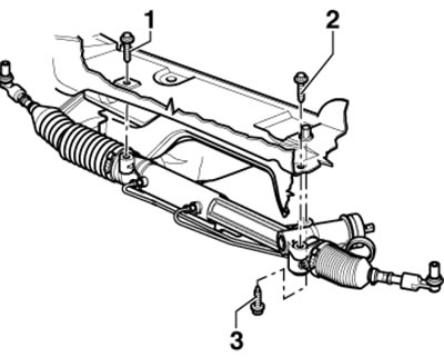
1. The steering gear installation details are shown in the illustrations.
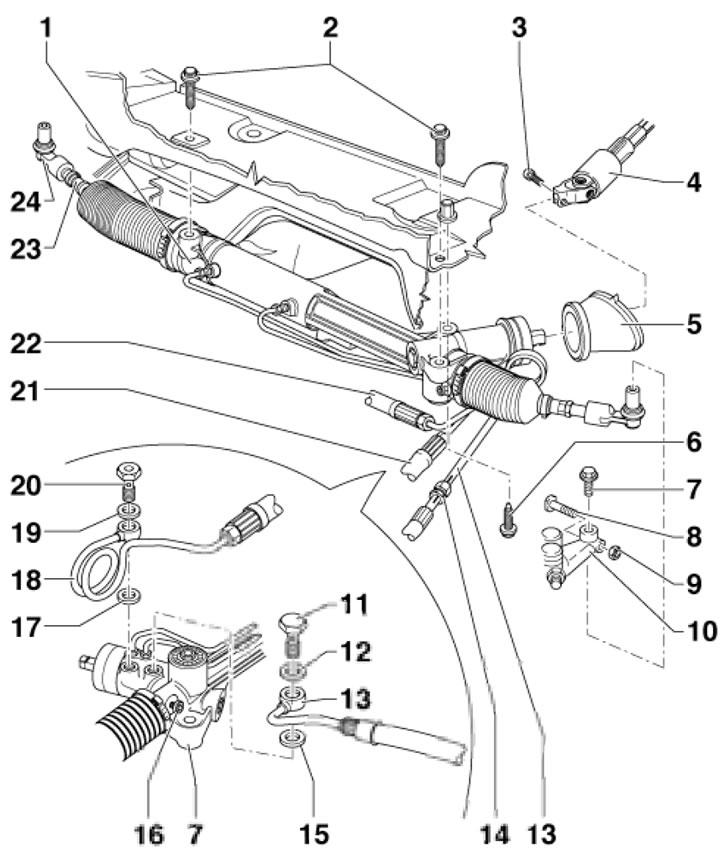
20.1a. Installation details of the power steering mechanism 1. Steering gear with rods and tips; 2, 6. Bolt with washer, subject to replacement, 40 Nm, then tighten to an angle of 90°; 1. Steering gear with rods and tips; 2, 6. Bolt with washer, subject to replacement, 40 Nm, then tighten to an angle of 90°; 3. Bolt, 30 Nm; 4. Steering column; 5. Seal in the engine compartment bulkhead; 7, 8. Bolt; 9. Self-locking nut; 10. Hub holder (steering knuckle); 11. Hollow bolt, 47 Nm; 12, 15. Sealing ring, subject to replacement; 13. Return hose; 14. Return hose connection, 40 Nm, colour mark facing up; 16. Threaded plug, 22 Nm; 17, 19. Sealing ring, subject to replacement; 18. Expansion hose; 20. Hollow bolt with non-return valve, 35 Nm; 21/22. Expansion hose for 4-/6-cylinder models; 23. Steering rod; 24. Steering tip with joint
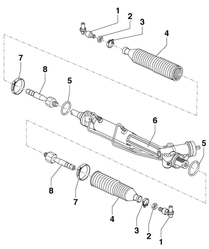
20.1b. Assembly parts of the power steering gear 1. Tie rod end with joint; 2. Lock nut, 40 Nm; 3, 7. Clamp, subject to replacement; 4. Dust cover; 5. Sealing ring, subject to replacement; 6. Steering mechanism; 8. Steering rod, 100 Nm

20.1c. Servotronic system parts 1. Steering gear with rods and tips; 2. Servotronic solenoid valve connector; 3. Holder for 9 relays (under the driver's footwell trim) with servotronic control unit (No. 2); 4. N119 servotronic solenoid valve with integrated shaped wiring harness; 5. Adapter wire; 6. Bolt 2.5 mm, 3 Nm; 7. Solenoid valve N119 servotronic with connector; 8, 9. Sealing ring, subject to replacement; 10. Mesh filter, subject to replacement
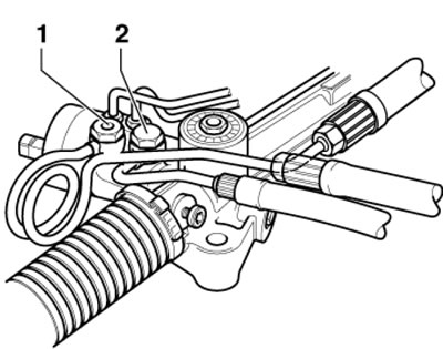
2. To set the steering gear to the center position, move the steering wheel slightly from the center position to the left/right so that the hole (arrow on the illustration) opposite the hole closed by the bolt (2). Ask an assistant to screw the VAS6224 bolt into the steering gear by hand instead of the standard bolt until you feel it enter the centering hole.
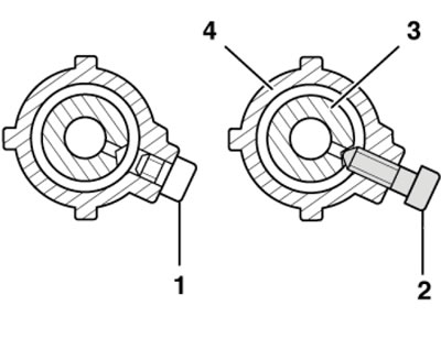
20.2. Setting the steering gear to the central position
3. To adjust the steering mechanism, lift the car on a platform and set the wheels to the straight-ahead position. The presence of excessive play can be judged by knocking when turning the steering wheel 30° from the center position. In this case, ask an assistant to carefully screw in the adjusting bolt (arrow on the illustration) until the knocking sound stops. Then test it on the road and make sure that the steering wheel returns smoothly to its original position on its own. Repeat the adjustment if necessary.
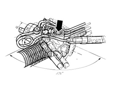
20.3. Adjusting bolt
4. The process of removing and installing the steering gear is described below.
Removal
5. Disconnect the negative battery cable. If necessary, remove the battery (see Chapter 5).
6. Remove the ignition switch with the steering wheel in the center position and turn it slightly to engage the steering column lock.
7. Remove the driver's storage compartment (see Chapter 11).
8. Loosen the bolt (see illustration 19.6) and secure the steering column so that its sections do not shift too much relative to each other (see Section 19).
9. Clamp the suction and return hoses with clamps 3094 (see illustration) and remove the front wheels.
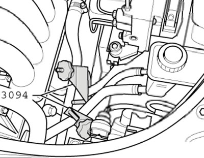
20.9. Pinched power steering hoses
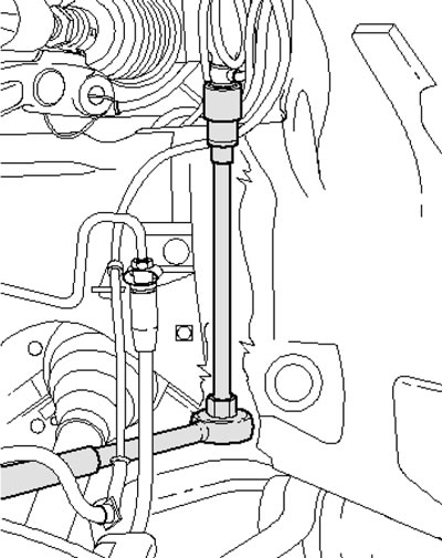
10. On the left side of the car, remove the suspension strut fastener to the control arm and place the stock (1 in the illustration) in front of the lever (2), looking in the direction of forward movement.
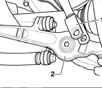
20.10. The suspension strut is separated from the supporting arm
11. On the left side of the car, loosen the nut (1 in illustration 4.7 Chapter 8), remove the bolt and pull both upper rods (2) upwards. Do not attempt to enlarge the slots in the wheel bearing holder using a chisel, etc. Remove the bolt (3) and disassemble the joint (4). Pull or press the tie rod end downwards from the steering knuckle, avoiding damage to the joint boot.
12. Attach the wheel bearing holder to the left side of the vehicle (1 in the illustration) on the stand (3) using a clamp (2).
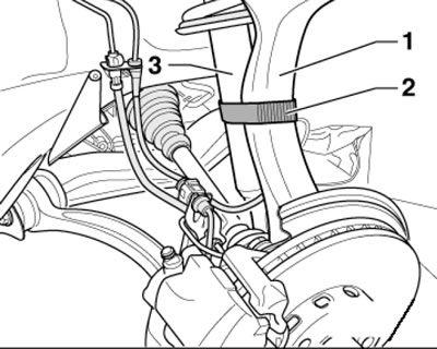
20.12. Fastening the bearing holder to the stand
13. Remove the nut (arrow on the illustration), press the latches, separate the wiring and remove the plastic cover.
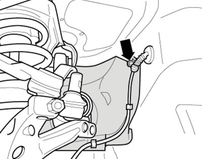
20.13. Removing the casing
14. Loosen the bolt (1 in the illustration) approximately 1 turn, unscrew the bolts (2 and 3). Tilt the steering gear forward on the driver's side.
20.14. Steering gear fastening
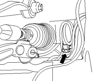
15. Remove the bolt (22 mm) of the return hose from the steering gear (see illustration). The bolt may be accessible through the wheel arch.
20.15. Unscrewing the hollow bolt of the return hose
16. Remove the bolt (19 mm) of the pressure hose from the steering gear (see illustration). The bolt may be accessible through the wheel arch.
20.16. Hollow bolt of pressure hose
17. Remove the bolt (1 in illustration 20.14) and remove the steering gear through the left wheel arch.
Installation
18. Center the steering gear (see paragraph 2).
19. Install the steering gear, screw in the bolt (1 in illustration 20.14) by hand and tilt the mechanism forward on the driver's side.
20. Connect the return (1 in the illustration) and pressure (1) hoses, tighten their hollow bolts with new seals. The hoses must not touch each other or other parts.
20.20. Fastening the power steering hoses
21. Install the seal into the bulkhead. Tighten the bolt (2 in illustration 20.14) by hand. Tighten the bolt (3), and then finally tighten the bolts (1 and 2).
22. Remove the steering column lock, set the steering wheel to the straight-ahead position and connect the steering column to the steering gear (see Section 19), then remove the clamps holding the steering column sections from the steering column.
23. Press the joints of both upper links into the wheel bearing housing and secure the suspension strut to the control arm, tightening the bolt by hand.
24. Insert the steering rod end into the steering knuckle by hand, assemble the connection (1 in illustration 4.7 Chapter 8), tighten the bolt (3).
25. Unscrew the VAS6224 centering bolt from the steering gear and screw the standard bolt into the inspection hole. Remove the clamps from the power steering hoses.
26. Install the battery, gutter cover and wheels
27. Tighten the suspension strut mounting bolt to the control arm.
28. Check and, if necessary, adjust the power steering fluid level. Bleed the power steering (see Section 21).
29. Check and, if necessary, adjust the wheel alignment angles.