



Table of contents: Main storage compartment ↓ Driver's storage compartment ↓ Panels and covers ↓ Ashtrays ↓ Cup holder or storage compartment in… ↓ Removal and installation of the… ↓ Removal and installation the center… ↓
Main storage compartment
1. The installation details of the main storage box are shown in the illustration.
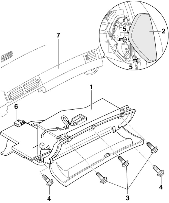
11.1. Main storage compartment installation details 1. Glove box; 2. Instrument panel end cover; 3. Bolts, 3 pcs., 5 Nm; 4, 5. Bolts, 2 pcs., 5 Nm; 6. Electrical wiring connector; 7. Instrument panel
2. To remove the glove box lock, open it, loosen the bolt (1 in the illustration) handles (2) on the side of the lid, pull the handle out of the lid, press the pin and remove the lock (1). The following describes how to remove the glove box
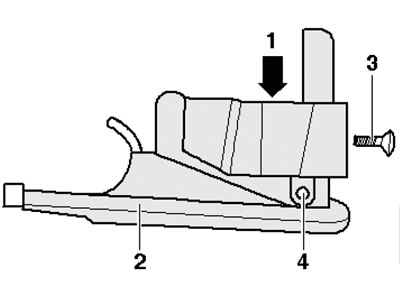
11.2. Removing the glove compartment lock
3. Remove the end cover on the right side of the instrument panel using tool 3370 (see illustration).
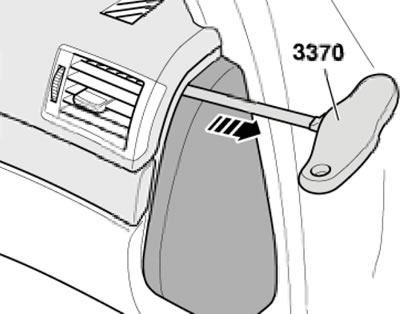
11.3. Removing the end cap
4. Open the glove box and loosen the three bolts (3 in illustration 11.1) at the top in the slot of the glove compartment. On the side, loosen two bolts (5) and from the footwell, loosen 2 bolts (4).
5. Pull out the glove box and disconnect the lighting connector. If there are other connectors in the glove box, (for example, the passenger airbag switch) disconnect them as well. If there is an airbag switch, remove it from the glove compartment.
6. Installation is carried out in the reverse order of dismantling the components.
Driver's storage compartment
7. The driver's storage box installation details are shown in the illustration. The removal and installation of this storage box is described below.
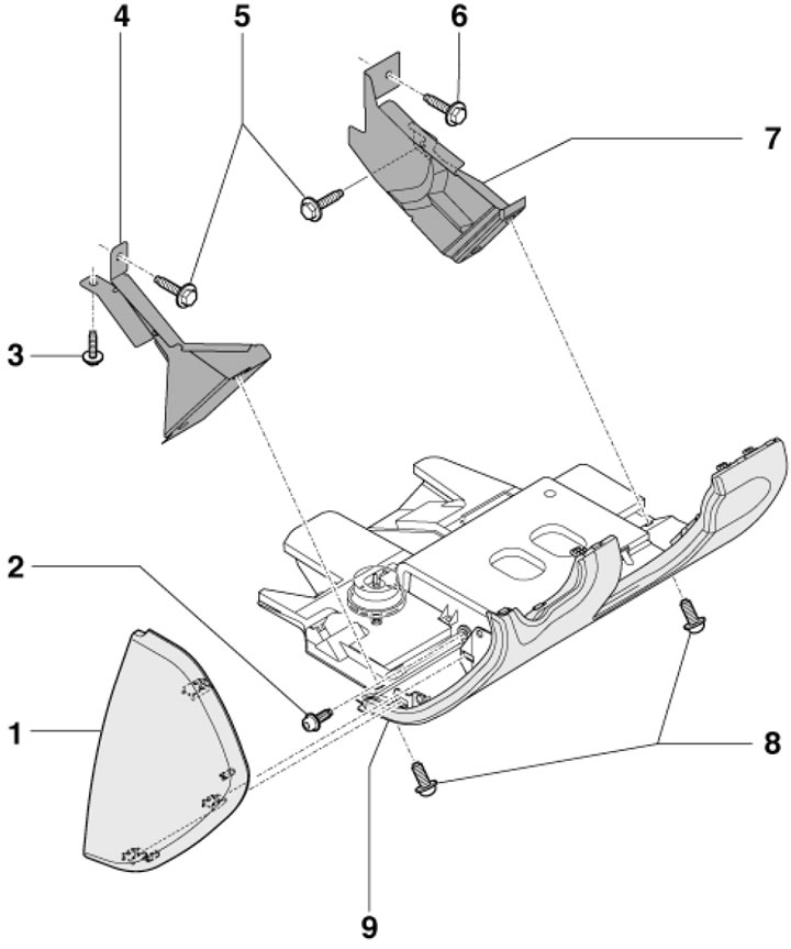
11.7. Driver's storage compartment installation details1. Instrument panel end cover; 2, 3. Bolt, 9 Nm; 4. Left support (only on models with knee rest seat); 5. Bolts, 2 pcs., 9 Nm; 6. Bolt, 9 Nm; 7. Right support (only on models with knee rest seat); 8. Bolts, 2 pcs., 9 Nm; 9. Driver's storage compartment
8. Remove the end cover on the left side of the instrument panel using tool 3370 (by analogy with illustration 11.3).
9. Remove the bolts (2 and 8 in Illustration 11.7), pull the top side of the glove box back and separate it.
10. Disconnect the diagnostic connector, disconnect the connector of the footwell lighting and the additional speaker (if available).
Panels and covers
11. To remove the lower instrument cluster trim, pull it backwards (see illustration).
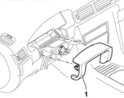
11.11. Removing the lower instrument cluster trim
12. To remove the steering column covers, remove the steering wheel (see Chapter 10), pull out and lower the steering column until it stops. Then remove the bolts (1 in illustration 19.3 Chapter 10), separate the upper casing (2) from the lower casing (1) and separate both sections. When installing, insert the upper casing into the hooks of the lower casing, press them together and install.
13. To remove the central armrest (1 in the illustration) remove the rear ashtray (see below), loosen the nut (4) in the ashtray socket and remove the armrest. On models with a telephone in the central armrest, you also need to disconnect the connector (2) by squeezing the latches (3).
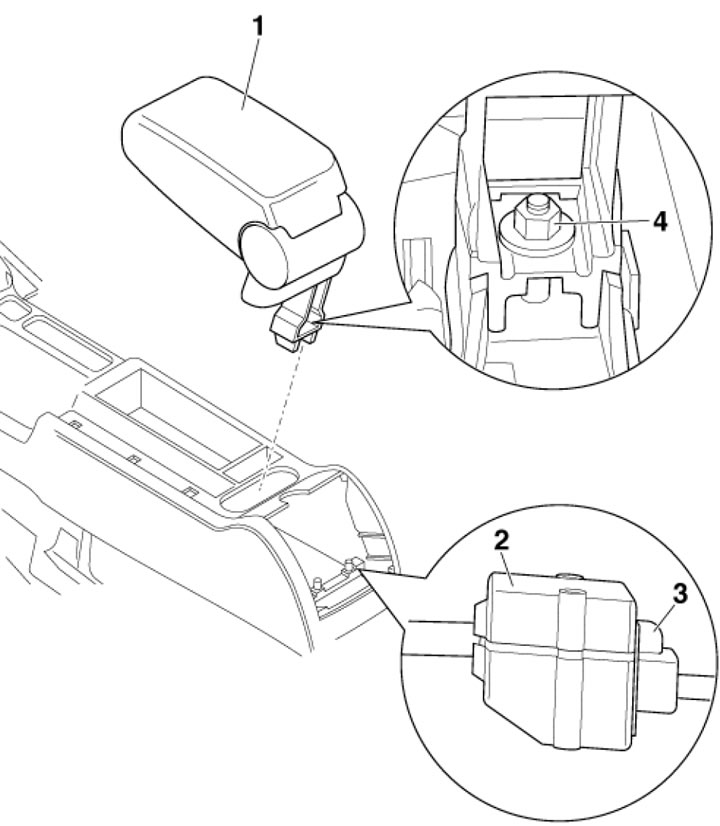
11.13. Central armrest installation details 1. Central armrest; 2. Connector; 3. Fixators; 4. Nut, 26 Nm
Ashtrays
14. To remove the rear ashtray, remove the cover from the clips (2 in the illustration), remove the rear ashtray (1) and, if present, remove the seat heating switch support (3).
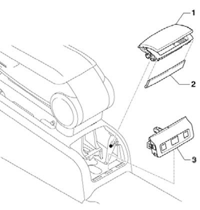
11.14. Rear ashtray installation details
15. The installation details of the front ashtray are shown in the illustration. Its removal is described below.
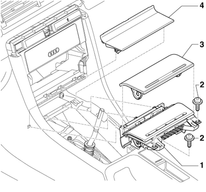
11.15. Front ashtray installation details 1. Front ashtray; 2. Bolts, 2 pcs., 5 Nm; 3. Ashtray lid; 4. Storage compartment lid
16. Pull out the audio block approximately 10 mm (see Chapter 12).
17. Remove the climate control panel (see Chapter 3).
18. Open the ashtray and remove the insert.
19. Remove the selector lever or gearshift lever trim panel. On models with manual transmission, additionally remove the lever boot (see chapter 6).
20. Remove the bolts (1 in illustration 11.15), lift the ashtray, disconnect the connector, separate the cover (3) from the ashtray and remove the glove compartment cover (4).
21. Installation is carried out in the reverse order of dismantling the components.
Cup holder or storage compartment in the center console
22. Open the main storage compartment and carefully separate the trim (1 in the illustration).
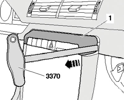
11.22. Removing the overlay
23. Pull the audio unit out approximately 50mm to release the ear cup frame.
24. Using a screwdriver, press down the latches (2 in the illustration) and simultaneously pull out the cup holder (1). Disconnect the cup holder/storage compartment connectors.
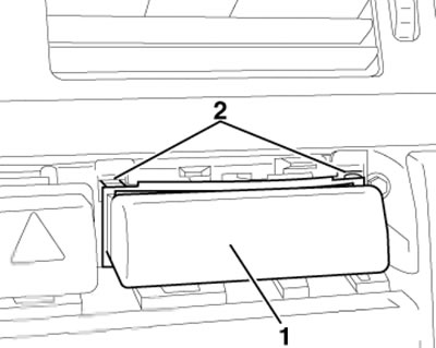
11.24. Cup holder/storage compartment latches
Removal and installation of the central section of the instrument panel
25. Remove the center console (see below) and the front ashtray (see above).
26. Remove the audio unit cover (see Chapter 12).
27. Remove the climate control unit (see Chapter 3).
28. Remove the trim on the cup holder (see above).
29. Remove the bolts (2 and 3 in the illustration), and remove the center section of the instrument panel.
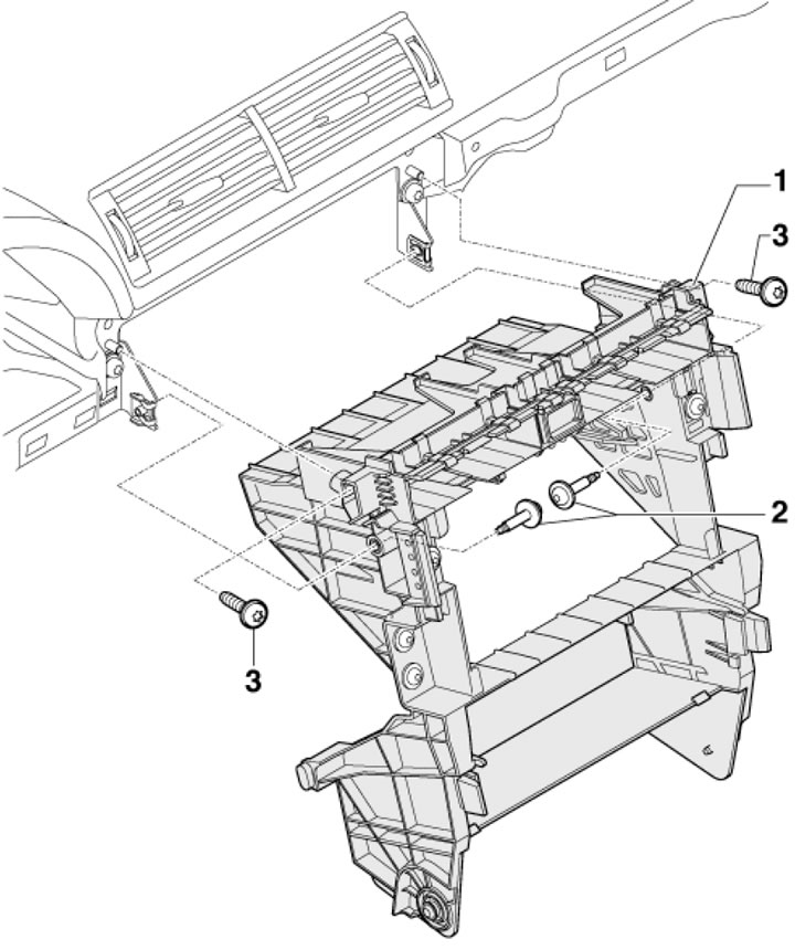
11.29. Bolts (2 and 3) for fastening the central section of the instrument panel (1)
30. Installation is carried out in the reverse order of dismantling the components. Tighten the bolts with a force of 5 Nm.
Removal and installation the center console
31. The details of the installation of the center console are shown in the illustration.
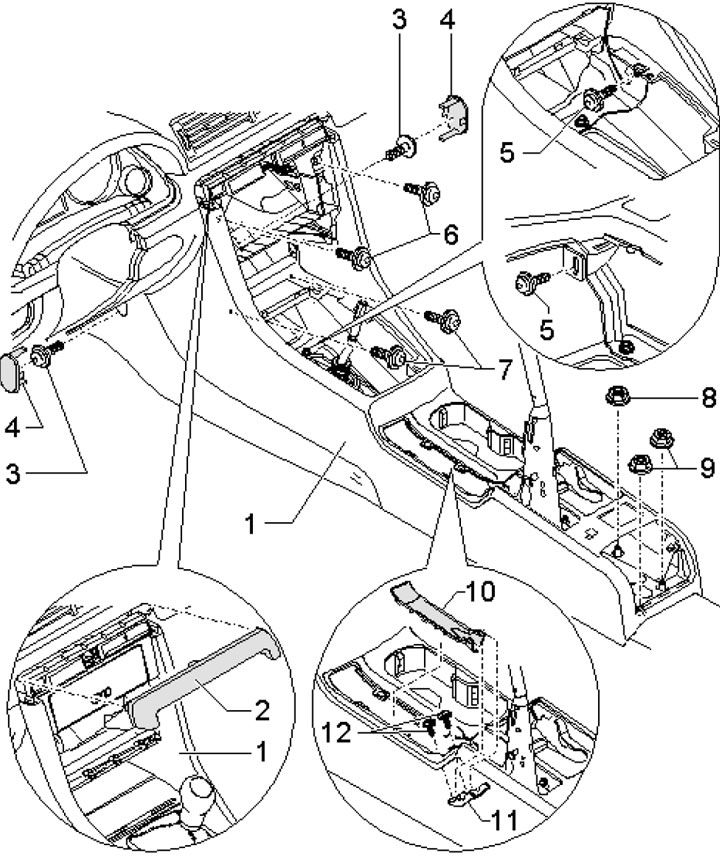
11.31. Center console installation details 1. Center console; 2. Switch cover; 3. Bolts. 2 pcs., 5 Nm; 4. Plugs, 2 pcs.; 5. Bolts. 4 pcs. 5 Nm; 6, 7. Bolts, 2 pcs., 5 Nm; 8. Nut with washer, 26 Nm; 9. Nut with washer, 2 pcs., 26 Nm; 10. Parking brake lever cover; 11. Connecting piece; 12. Bolts, 2 pcs., 1 Nm
32. Remove the center armrest (see above).
33. Remove the cover on the selector lever/gear shift lever.
34. Remove the audio unit (see Chapter 12) and the climate control unit (see Chapter 3).
35. Remove the switch cover (2 in illustration 11.31), set the parking brake.
36. On models with AT/CVT, move the selector lever to the rearmost position.
37. Remove the plugs on both sides of the center console (4 in illustration 11.31) in the foot blocks and unscrew the bolts (3) located underneath them.
38. Remove the parking brake lever trim panel.
39. Carefully lift the overlay (10 in illustration 11.31) from the center console, starting from the front.
40. Loosen the bolts (12 in illustration 11.31) and remove the connecting piece (11), otherwise the trim cannot be passed through the parking brake lever.
41. Remove the front ashtray and cigarette lighter (see above).
42. Remove the bolts (5-7 in illustration 11.31). On models with a center armrest, loosen the nut and washer (11). Loosen the two nuts (12) and pull the center console firmly backwards.
[This publication is borrowed from the resource: AUDImanual]