
Table of contents: Hood lock holder ↓ Gutter Cover and Windshield Lower… ↓ Wing ↓ Soundproofing panels ↓ Wheel arch liner ↓ Front bumper ↓
Hood lock holder
1. The installation details of the hood lock holder are shown in the illustration.
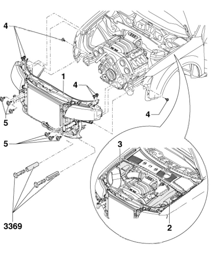
2.1. Bonnet Lock Holder Installation Details 1. Hood lock holder; 2/3. Left/right engine covers; 4. Bolt with washer, 10 Nm; 5. Bolt with washer, 50 Nm
2. A description of how to bring the hood lock holder into the service position is presented in Chapter 2. The removal and installation process is described below.
3. Remove the front bumper (see below) and sound insulation (see the relevant subsection below).
4. Separate the Bowden cable from the hood lock (see Section 3) and remove the left and right engine covers (2 and 3 in Illustration 2.1).
5. Remove the screws securing the air duct to the air cleaner from the hood lock holder.
6. Disconnect the electrical wiring connectors, drain the coolant and disconnect the engine cooling system hoses.
7. Separate the air conditioning system condenser from the radiator (see Chapter 3), without disconnecting the refrigerant lines from it, and secure the capacitor to the wire.
8. Disconnect the hoses from the power steering fluid radiator and remove it.
9. On AT/CVT models, disconnect the pipes from the ATF cooler.
10. On models with an intercooler, disconnect the air duct.
11. Disconnect the hood seals at the joints between the wing and the hood latch holder.
12. Remove the bolts (5 in illustration 2.1) and ask an assistant to hold the hood lock holder. Then unscrew the bolts (4) and remove the hood lock holder.
13. Installation is performed in the reverse order of dismantling the components. After installation, adjust the headlight angle. The hood lock holder should be centered between the wings.
Gutter Cover and Windshield Lower Trim Panel
14. The installation details of the gutter cover and windshield lower trim panel are shown in the illustration.
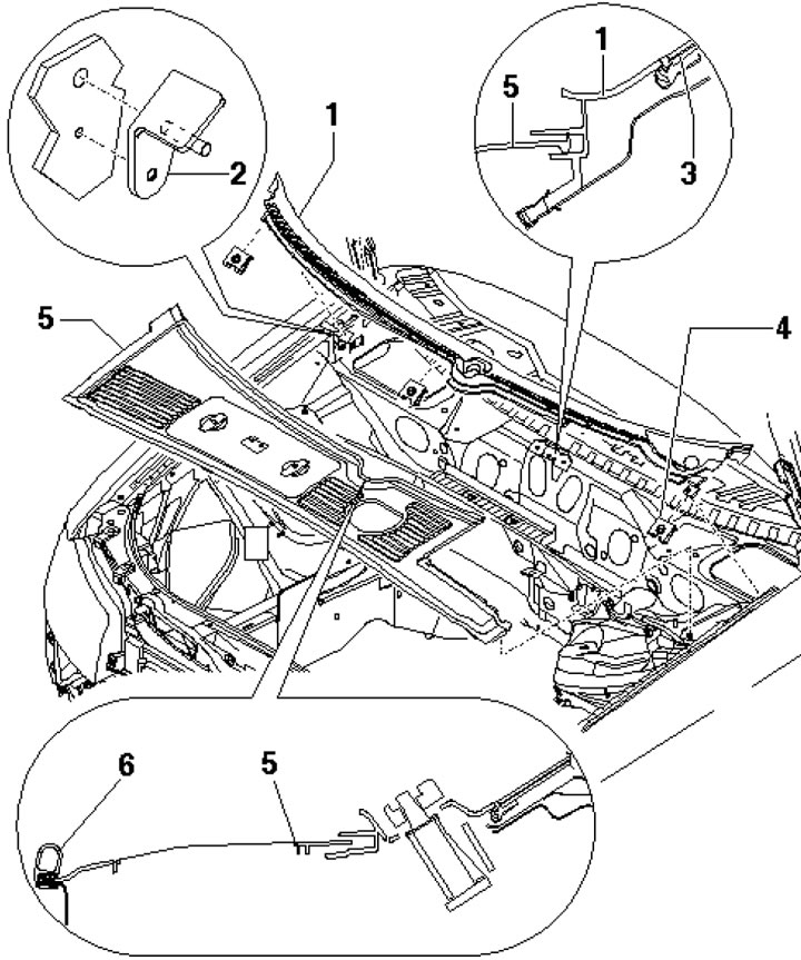
2.14. Lower windshield trim panel 1. Lower windshield trim panel; 2. Support; 3. Windshield; 4. Staples; 5. Gutter cover; 6. Compaction
15. To remove the gutter cover, remove the seal (6) and pull the cover (5) out of the panel (1).
16. To remove the panel (1), remove the windscreen wiper arms and cover (5). Remove the clips (4), pull the panels out of the retaining strip at the bottom of the windscreen and remove it with an upward movement.
Wing
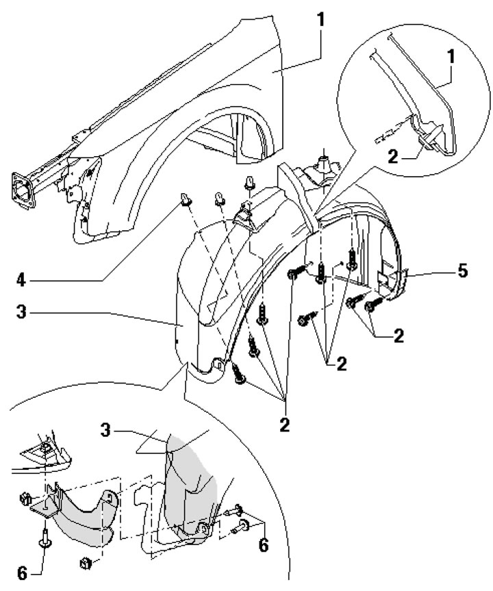
17. The front wing installation details are shown in the illustration. The following describes the removal and installation of the wing.
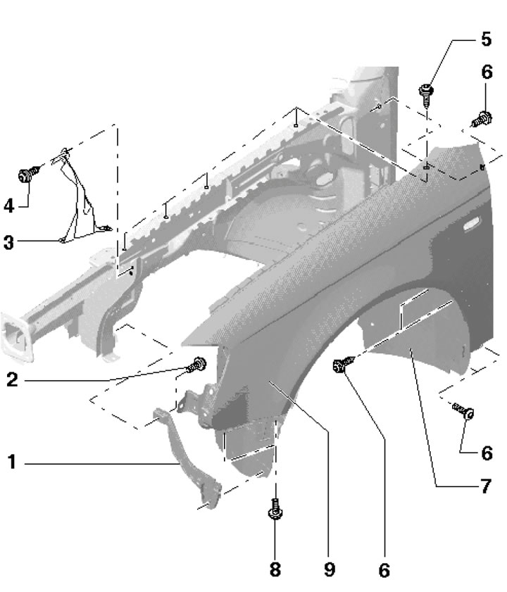
2.17. Wing installation details 1. Bracket for wheel arch liner; 2, 4. Bolt with washer, 10 Nm; 3. Wing bracket; 5. Bolt, 10 Nm; 6. Bolt with washer, 8 Nm; 7. Wheel arch liner; 8. Bolt with washer, 10 Nm; 9. Wing
18. Remove the front bumper (see subsection below), wheel arch liner (see the relevant subsection below).
19. Remove the end plate. To do this, with the wheel arch liner removed, unscrew the bolts (1 in the illustration) from the spacer bushings (3) and remove the plate (2) from the wing (4).
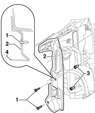
2.19. End plate fastening
20. Remove the corresponding headlight unit and disconnect the connectors for the turn signal repeater (see Chapter 12).
21. Remove the bolts (5, 6 and 8 in Illustration 2.17) and remove the wing.
Soundproofing panels
22. Details of installation of soundproofing panels are shown in the illustration.
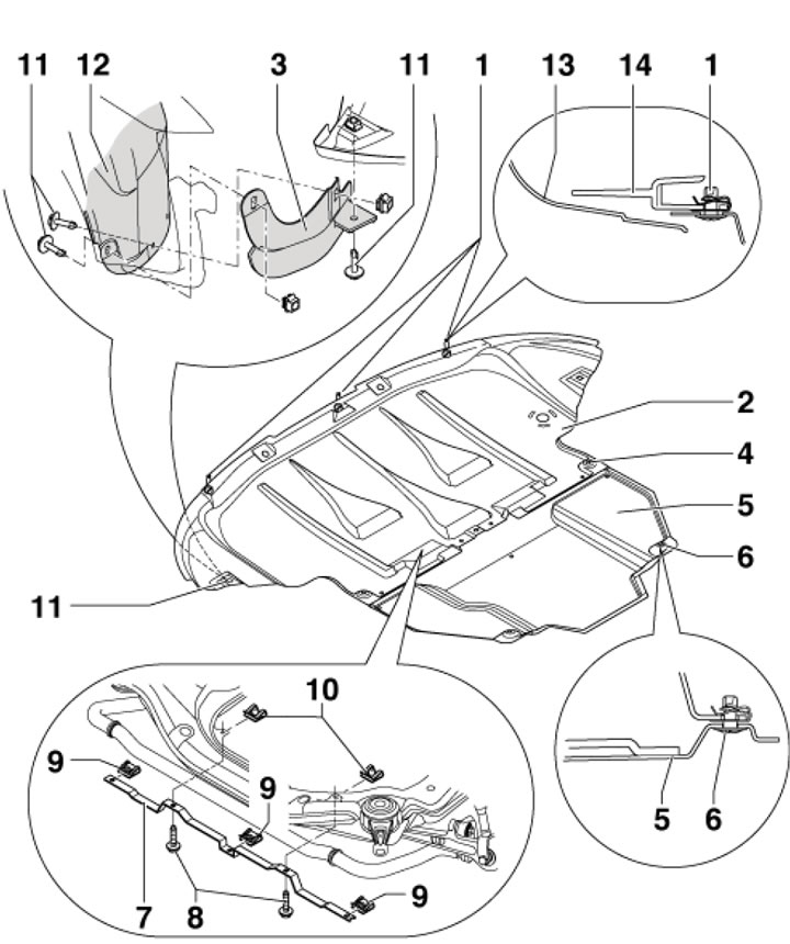
2.22. Soundproofing panels 1, 4. Quick release screw, 3 pcs.; 2. Front sound insulation; 3. Wheel spoiler; 5. Rear sound insulation (on some models); 6. Quick release screw, 2 pcs.; 7. Soundproofing support, marks (recesses) must be facing the left side; 8. Bolt, 2 pcs., 7 Nm; 9. Special nut, 3 pcs.; 10. Special nut, 2 pcs.; 11. Clamping pin; 12. Wheel arch liner; 13. Bumper; 14. Hood lock holder
Wheel arch liner
23. The details of the locker installation are shown in the illustration.
2.23. Front wheel arch liner installation details 1. Wing; 2. Bolt, 2.3 Nm; 3. Front wheel arch liner; 4. Expansion nut; 5. Threshold overlay; 6. Quick release screw
24. To remove the liner, remove the wheel, unscrew the screws (6) and bolts (2), separate the liner from the wing and pull the liner down.
Front bumper
25. The bumper installation details are shown in the illustration.
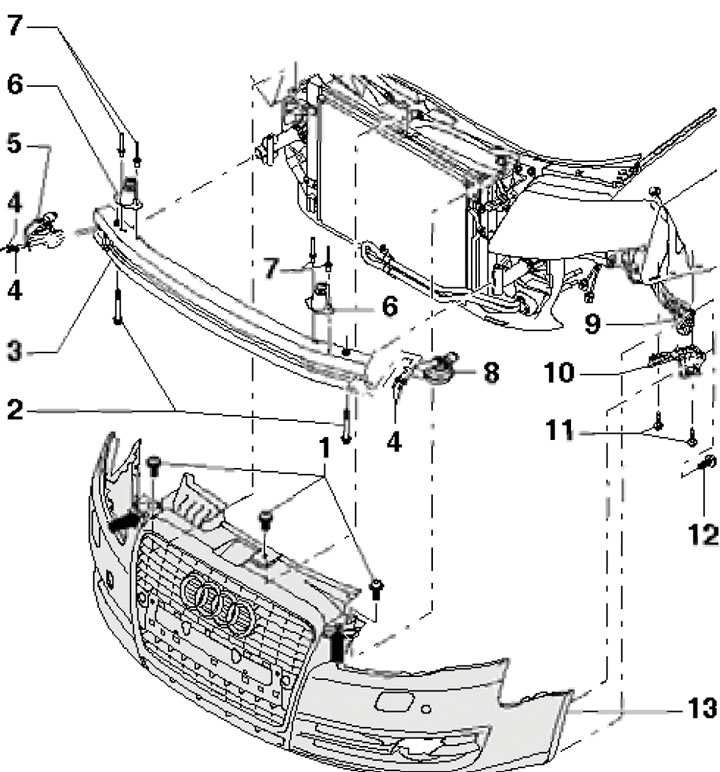
2.25. Front bumper installation details 1. Bolt with washer, 6 Nm; 2. Bolt, 23 Nm; 3. Bumper (beam); 4. Rivet; 5. Horn; 6.Support; 7. Rivet; 8. Horn; 9. Wing mounting bracket; 10. Guide; 11. Bolt, 1 Nm; 12. Combination bolt, 1 Nm; 13. Bumper cover