
Table of contents: Cars with a four-cylinder engine ↓ Cars with 6-cylinder engine ↓
When working with the generator, you should follow the rules that are constantly found in different chapters of this book. After disconnecting the negative battery cable, it is best to tape the negative pole, do not dismantle the generator with the battery connected, and remember the coding when dismantling (radio receiver and radio navigation system), after installing the generator, reactivate the corresponding devices.
Self-disassembly and installation of the generator is not such a simple matter. The volume of this complex work is determined by the design of the generator holder and the method of disassembling the poly V-belt. Disassembly is fundamentally different in cars with four- and six-cylinder engines.
Cars with a four-cylinder engine
1. Removal: Open the coolant expansion tank cap. Since hot steam may escape when opening the cap, cover the cap with a cloth, then carefully open the cap.
2. Remove the engine cover. In cars with independent heater, unscrew the three screws securing the heater pipe on the noise-insulating cover.
3. Remove the noise-insulating cover by loosening it at ten points. Place a tray under the engine to collect the liquid (V.A.G. 1306).
4. Remove the retaining clip 1 and remove the coolant temperature sensor (G2) 2
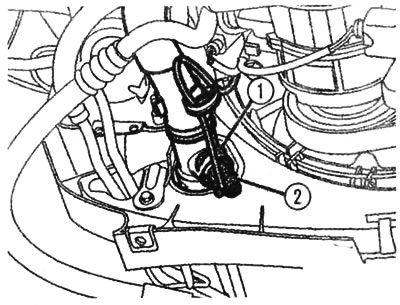
Locking bracket 1 and coolant temperature sensor 2
5. Drain the coolant from the radiator only. Then remove the hose from the cooling system pipe (arrow).
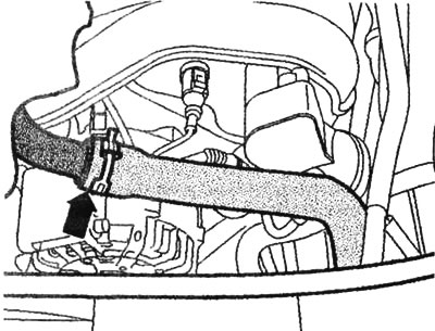
Hose on the cooling system pipe. The hose is removed at the location indicated by the arrow
6. Unscrew the radiator fan control unit (arrow), remove it and set it aside.
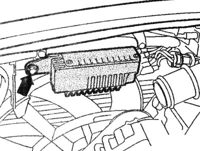
Mounting screw (arrow) on the control unit for the radiator fan
7. Turn the poly V-belt tensioner in the direction of the arrow to loosen the belt.
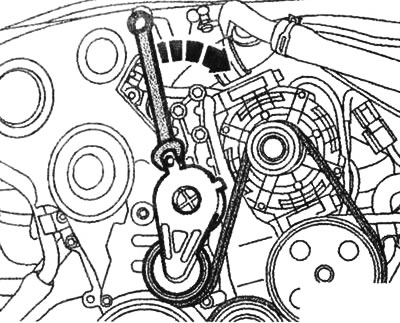
The tensioner of the poly V-belt must be turned in the direction of the arrow
8. Remove the poly V-belt from the generator pulley and loosen the tensioner.
9. Disconnect connector 1 and, for a 2.0L engine, also connectors 2 and 3.
10. Remove the 4 mounting screws and remove the generator. Unscrew the D+ terminal.
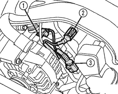
Plug connections on the generator: 1, and also (in case of 2.0 l engine) 2 and 3
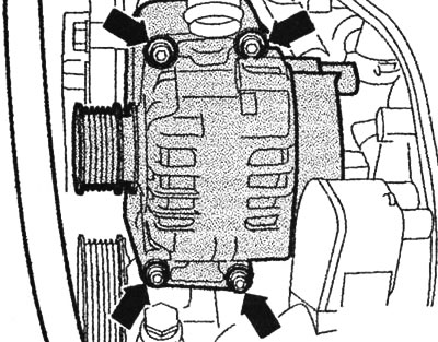
The arrows indicate the upper and lower generator mounting screws
11. Installation is carried out in the reverse order. Be sure to pay attention to the accuracy of the fit and the passage of the poly V-belt.
When installing the generator, pay attention to the accuracy of the fit and the passage of the poly V-belt
12. Fill with coolant, when connecting the battery, do not forget to activate the corresponding devices.
Cars with 6-cylinder engine
1. Dismantling: Remove the upper engine cover at an angle upwards. Open the poly V-belt. Before removing the belt, mark the direction of the belt with chalk or a felt-tip pen. If the old belt is installed in the opposite direction, it may fail.
2. To loosen the belt, turn the tensioner in the direction of the arrow (3299, 3299/1).
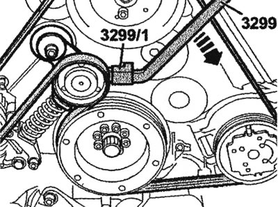
The tensioner of the poly V-belt must be turned in the direction of the arrow
3. Remove the belt from the steering pump pulley. In the case of a car with an independent heater, unscrew the three screws of the heater pipe on the noise-insulating cover. Remove the noise-insulating cover by loosening it at ten points.
4. Disconnect both cable clamps at the locations indicated by the arrows. Open the intake pipe holder and remove the electric wire.
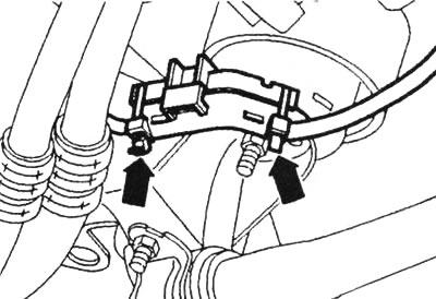
Disconnect the cable ties at the points shown by the arrows
5. In vehicles with automatic transmission, remove the holder for the working fluid pipes. To do this, unscrew nuts 1 and 2.
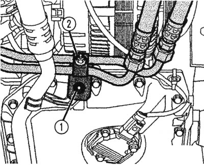
In cars with automatic transmission, remove the holder for the working fluid lines by unscrewing nuts 1 and 2
6. Remove the wires from the generator (see description of operation 9 for 4-cylinder engines). Remove the mounting screws and remove the generator.
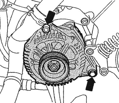
The arrows show the generator mounting screws
7. Installation is carried out in the reverse order. Pay special attention to the accuracy of the fit and the passage of the poly V-belt.
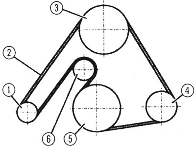
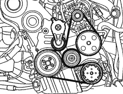
Poly V-belt passage: 1 - generator, 2 - poly V-belt, 3 - vane pump for power steering, 4 - air conditioning compressor, 5 - crankshaft, 6 - tension roller.
8. Tightening torques during installation: generator to engine: M8 - 22 Nm, M10 - 45 Nm, terminal 30/B+ on the generator - 16 Nm, terminal on the battery pole - 6 Nm. Start the engine and check the belt routing. After connecting the battery, activate the appropriate devices.