
Repair Chevrolet Repair Toyota Repair Honda Repair AvtoVAZ Repair Mercedes-Benz Repair BMW Repair Opel
Home  |  Contacts  |  Sitemap  |    
English Русский
Български
Беларускі
Український
Српски
Hrvatski
Română
Polski
Slovenský
Magyar
AudiManual.ru


  • AUDI 80
  • AUDI 100
  • AUDI A3
  • AUDI A4
  • AUDI A6
  • AUDI A8
  • AUDI Q
  • OTHER
  • ARTICLES
B8 (2007-2015) B7 (2004-2008) B6 (2000-2006) B6 (2000-2006, petrol) B5 (1994-2001) B5 (1994-2001, petrol)

Electric power windows (Audi A4 B5)

  • Home
  • Audi A4
  • B5 (1994-2001, petrol)
  • Electrical equipment
  • Tools and devices
  • Electric power windows
            0
Table of contents: Malfunctions ↓ Table of measuring values for window… ↓ Temporary roadside assistance ↓ Replacing the window lift motor ↓
The operating mode of the window lifters is determined not only by the switches, but also by the window lifter control unit on the support with additional relays on the left under the dashboard.

Functioning: when the ignition is on, the glass in the driver's door or the passenger's door next to the driver slides up or down until it stops by briefly pressing or releasing the switch. The glass movement is stopped by briefly pressing the button in the opposite direction.

For safety reasons, this convenient way of switching on the rear doors only exists for lowering the glass.

When the ignition is off, when you press the button, all windows move down to the stop only. The glass moves up only if the window lifter button is pressed.

Child protection: the electric windows in the rear doors are locked by a central switch in the driver's door armrest.

Anti-theft device: if the driver's door is opened and closed again with the engine off, all windows are disabled.

Comfortable closure: in all cars with electric windows, they can be closed simultaneously when the driver's door and the passenger door next to the driver are closed. To do this, hold the key in the "closed" position for a little longer. If there is an electric sliding roof, it also closes at the same time.

Jam protection: If the glass encounters an obstacle while moving upward, it immediately begins to move in the opposite direction and drops a few centimeters.


Malfunctions


1. If neither glass moves, check the circuit breakers in slots 22 and 23 in the "8-way relay support" on the left under the instrument panel for continuity.

2. Checking the switches: If only one window lifter does not work, try to operate it from the second switch.

3. This way you can determine whether the source of the fault is in the first switch.

4. This test cannot be performed with the driver's door glass. Remove the door trim.

5. For the sake of experiment, swap the switch connectors so that the driver's door glass is activated by a switch that is definitely working.

6. Checking the supply wire: If the switch is OK, then disconnect the wire connector in the window lifter motor and check the connector with a voltmeter to see if the correct signals are actually being sent to the window lifter.

7. If the voltage readings are correct, then the source of the defect remains the window lift motor.

8. But if there is no voltage supplied to the engine, then check the wire and the control unit.

9. Poor glass movement may be due to a jammed window guide.

Table of measuring values for window lifters


The table shows the nominal values using the driver's door window lift as an example (cars with four windows).

On the rear windows and in cars with two power windows, wires of other colors are partially laid (see footnotes).

Terminal
Wire color
Measurement relative to
Condition
Nominal value
It is measured
1
Red/gray
"masses"
"Ignition on" or door not closed since last time "Ignition on"
Approx. 12 V
Voltage from the control unit
2
White/yellow
masses
no
Approx. 12 V
Voltage of the signal "Central closing"
2
White/yellow
masses
Holding the key in the door lock in the "Closed" position
Approx. 12 V
Voltage of the signal "Central closing"
3
Yellow/blue 1)
masses
"Ignition on" or door not closed since last time "Ignition on"
Approx. 12 V
Switch signal "Window open"
4
Black/Yellow 2)
masses
"Ignition on" or door not closed since last time "Ignition on"
Approx. 12 V
Switching signal "Window closed"
5
Black
masses
"Ignition on."
Approx. 12 V
Voltage from ignition switch
6
Brown
"+"
no
Approx. 12 V
Connection to ground
7
Red/green
masses
no
Approx. 12 V
Constantly±


1) or green/yellow, or white/black
2) or black/red, or white/black, or white/purple

Temporary roadside assistance


There is no mechanical override for power windows. But if your windows don't work, you don't have to drive with the window open:

1. If the switch is faulty, try to close the window using the second switch.

2. If it didn't work (for example, in the driver's door), then remove the switch of the other window or connect the connecting wire to the second, working switch (about dismantling switches in this chapter above).

3. With this working switch you will be able to close the window.

4. If the window lift motor is faulty, it can be removed by removing the door trim. To do this, loosen the clamping connection between the window and the window lift (screws on the back - chapter Body parts).

5. Now slide the glass up and fix it in this position using adhesive tape or a wooden wedge.

Replacing the window lift motor


The window lift motors are removed in the same way as the mechanical lifts (chapter Body parts). When installing a window lift motor, programming the stops is important:

1. Turn on the ignition.

2. Using the switch, lift the glass up to the stop.

3. Now hold the switch in the "up" position several times for a second.

4. Check: press the switch to the "down" position. Now the glass should go down by itself until it stops.

5. Electric motor repair is not provided.
5. Electric motor repair is not provided.


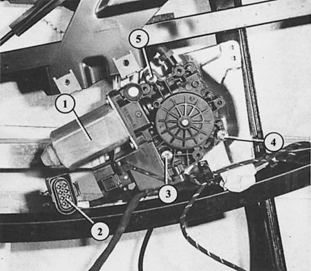
Electric window motor (1) with disconnected connector (2) and three mounting screws (3-5).


Electric window motor (1) with disconnected connector (2) and three mounting screws (3-5).


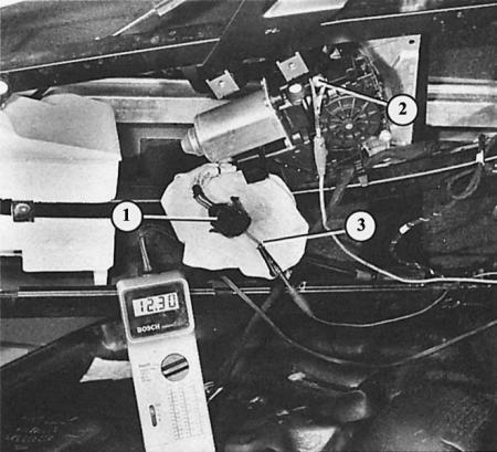
Here the connector (2) of the window lift motor (1) has been removed in order to check using a voltmeter and a test wire (3) whether the correct signals are being sent to the window lift.

(This article was previously published on the resource: Audimanual.ru)
The article was checked by auto expert Georgy Rodionov
This article is available at russian, bulgarian, belarusian, ukrainian, serbian, croatian, romanian, polish, slovak, hungarian

Share information:
Previous articles
Audi A4 B5: Tools and devices
Next articles

Central lock
Electrically adjustable mirror
Headlight washer system
Filling with windshield washer fluid
Electric sliding/removable roof
Radio receiver — dismantling
Antenna on the rear window


Similar articles on other Audi car models:
Electrical connection diagram for windows with electric window… Audi 80 B3 (1986-1991, petrol)
Electric power windows Audi 100 C3 (1982-1990)
Electric windows and rear view mirrors Audi A3 Type 8L (1996-2003)
Electric windows Audi A6 C5 (1997-2004)
Electric windows Audi A8 D2 (1994-2002)
Parts and components of the power supply system Audi Q5 Type 8R (2008-2017)
Power steering — general information Audi A2 (1999-2005)
Link to this page in different formats


Visitor comments

No comments yet


How much will 24 + 25 =


A4(B8, 2007-2015) 
  • General information
  • Operating instructions
  • Power unit
  • Petrol engines 1.8 l
  • Petrol engines 1.8/2.0 l
  • Petrol engines 3.0 l
  • Petrol engines 3.2 l
  • Fuel system (petrol)
  • Diesel engines 2.0 l (CA*)
  • Diesel engines 2.0 l (CJCB)
  • Diesel engines 2.7/3.0 l
  • Diesel engines 3.0 l
  • Fuel system (diesel)
  • Transmission
  • Manual gearbox 0B1
  • Manual gearbox 0B2
  • Manual gearbox 0B3
  • Manual gearbox 0B4
  • Automatic transmission 0B5
  • Automatic transmission 0B6
  • Automatic transmission 0AW
  • All-wheel drive system
  • Chassis
  • Front suspension
  • Rear suspension
  • Brake system
  • Steering system
  • Body
  • Exterior
  • Interior
  • Seats
  • Doors, locks and windows
  • Security system
  • Heating and air conditioning
  • Electrical equipment
  • Audio system
  • Power devices
  • Equipment and devices
  • Lighting and lamps
  • Electrical circuits
 
A4(B7, 2004-2008) 
  • General information
  • Introduction to manual
  • Troubleshooting
  • Operating instructions
  • Maintenance
  • Power unit
  • Petrol engines 2.0 (ALT)
  • Petrol engines 2.0 (TFSI)
  • Petrol engines 1.8 (MPI)
  • Diesel engines
  • Cooling system
  • Air conditioner
  • Fuel and exhaust system
  • Ignition system
  • Starting and charging
  • Transmission
  • Clutch
  • Manual gearbox
  • Automatic gearbox
  • Drive shafts
  • Chassis
  • Brake system
  • Front suspension
  • Rear suspension
  • Steering
  • Body
  • Exterior
  • Interior
  • Electrical equipment
  • Equipment and devices
  • Lighting and signaling
  • Windscreen wipers and washers
  • Electrical diagrams
  • Electrical diagrams (since 2007)
 
A4(B6, 2000-2006) 
  • General information
  • Vehicle Description
  • User manual
  • Maintenance
  • Power unit
  • Gasoline engine
  • Diesel engine
  • Lubrication system
  • Cooling system
  • Supply system
  • Injection system
  • Exhaust system
  • Ignition and control
  • Transmission
  • Gear box
  • Clutch and drive shafts
  • Chassis
  • Brake system
  • Car suspension
  • Steering
  • Body
  • Heating and ventilation
  • Exterior (external elements)
  • Interior (internal elements)
  • Electrical equipment
  • Power devices
  • Lighting and appliances
  • Electrical circuits
 
A4(B6, 2000-2006, petrol) 
  • General information
  • Introduction to the guide
  • Car care
  • Power unit
  • Engine repair
  • Lubrication system
  • Cooling system
  • Injection and control system
  • Ignition system
  • Power and exhaust system
  • Transmission
  • Clutch and drive shafts
  • Car gearbox
  • Chassis
  • Suspension and wheels
  • Steering
  • Brake system
  • Body
  • Interior
  • Exterior
  • Electrical equipment
  • Equipment and devices
  • Lighting and signaling
  • Power devices
  • Electrical circuits
 
A4(B5, 1994-2001) 
  • General information
  • Introduction to the guide
  • Car care
  • Maintenance (gasoline)
  • Maintenance (diesel)
  • Power unit
  • Gasoline engines
  • Diesel engines
  • Engine overhaul
  • Cooling system
  • Fuel injection (gasoline)
  • Fuel system (diesel)
  • Exhaust system
  • Ignition system
  • Transmission
  • Clutch
  • Mechanical gearbox
  • Automatic gearbox
  • Drive shafts
  • Chassis
  • Brake system
  • Car suspension
  • Steering
  • Body
  • Exterior
  • Interior
  • Doors, locks and windows
  • Heating and ventilation
  • Electrical equipment
  • Power devices
  • Equipment and devices
  • Electrical circuits
 
A4(B5, 1994-2001, petrol) 
  • General information
  • Vehicle description
  • Maintenance
  • Power unit
  • Engine repair
  • Turbocharging
  • Exhaust system
  • Cooling system
  • Ignition system
  • Fuel system
  • Motronic injection system
  • MPI and MPFI injection system
  • Transmission
  • Clutch
  • Gearbox and shafts
  • Chassis
  • Steering
  • Car suspension
  • Brake system
  • Wheels and tires
  • Body
  • Heating and ventilation
  • Body parts
  • Electrical equipment
  • Fuses and relays
  • Power devices
  • Lighting and lamps
  • Tools and devices
  • Electrical circuits
 
AudiManual.ru © 2017-2026 · Mobile version · Feedback · Sitemap: EN BG BY UA RS HR RO PL SK HU · Site search · News and articles
80 B2 · 80 B3 petrol · 80 B3 · 80 B4 · 100 C3 diesel · 100 C3 petrol · 100 C3 · 100 C4 petrol · 100 C4 · A3 Type 8L · A4 B5 petrol · A4 B5 · A4 B6 petrol · A4 B6 · A4 B7 · A4 B8 · A6 C4 · A6 C5 · A6 C5 Allroad · A8 D2 · Q5 Type 8R · Q7 Typ 4L · Audi A2 ·
This site uses cookies 🍪. Click the button to accept this fact.