



Table of contents: Checking the central lock ↓ Electrical Troubleshooting ↓ Troubleshooting a Pneumatic System ↓
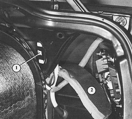
Emergency release of the fuel filler flap if the central locking system is faulty: remove the right-hand luggage compartment trim, fold back the insulating plate (2), press the fastening clip (1) of the central locking servomotor and pull the actuator back.
All doors, the trunk lid and the fuel filler cap, as well as the lock in the trunk lid, are opened and closed by turning the key in the driver's door lock or in the passenger door lock next to the driver. The main link in the system is the so-called dual pressure pump, which is driven by an electric motor. When the key is turned to the "open" position, the pump creates increased pressure, as a result of which various switching elements in the car remove the current lock.
The dual injection pump combines the central locking control unit and the anti-theft alarm control unit, if installed in the vehicle.
The following describes the serial central lock. The functions of more expensive systems with anti-theft devices, interior protection, infrared remote control (see also chapter Electrical equipment) in their basic function are also based on this system, as is the "central security lock".
Tip: A special feature of the boot lock: in the vertical position, the boot lock is always closed – regardless of the central lock. This prevents the boot from being opened by nimble thieves when stopped at a traffic light. In the horizontal position, the boot lock reacts to the central locking completely normally.
Checking the central lock
1. Close the driver's door and the passenger's door next to the driver or the trunk lid and open it with the key.
2. The central lock must be activated from all three locks.
3. After about two seconds, all locks should be locked.
4. If the pump runs for more than five seconds, the system is leaking – in this case, the dual injection pump can run for a maximum of 35 seconds, after which it should switch off.
Tip: If the central locking system fails one day, the doors and boot lid can be opened and closed as usual with the key. The door locking buttons can also be operated manually. Only the fuel filler flap must be unlocked separately: remove the right-hand boot trim. Press the retaining clip of the central locking motor of the fuel filler flap and pull the actuator back.
Electrical Troubleshooting
The following description also applies to vehicles with standard central locking. The electrical test is carried out on the 6-pin and 12-pin plug connector on the dual injection pump. In vehicles with an anti-theft alarm system there is an additional 16-pin connector on the pump, which is ignored during the test.
If the pump does not work when you turn the key in the driver's door lock, the passenger door next to the driver, or in the trunk lock, then:
1. Check the fuse.
2. Remove the trunk trim at the rear and on the right side; the dual pressure pump is located on the lower right side near the bottom of the trunk and is packed in foam.
3. Unpack the dual injection pump.
Important: First, disconnect the multi-pin connector with thin wires from the pump - lastly, the connector with thick wires (current supply).
4. Remove the 12-pin connector shell
5. Checking the switch element in the driver's door: connect the test lamp to the connector between the green/blue wire contact and the body ground.
6. The indicator lamp should be constantly on if the driver's door is opened with the key. In this case, the normally open contact is OK.
7. If the lamp does not light, then the normally open contact in the driver's door is faulty or there is no conductivity in the supply wire.
8. Switch the test lamp: instead of ground, one of the test lamp contacts is connected to the "+" of the battery. The other contact remains connected to the connector (green/blue wire contact).
9. Close the driver's door with the key.
10. If the control lamp now lights up continuously, the closing contact of the switching element is OK.
11. If the lamp does not light and there is no defect in the wire, then the switching element is faulty.
12. Checking the switching element in the passenger door next to the driver: in the disconnected pump connector, connect the test lamp between the yellow/blue wire contact and the body ground.
13. The indicator lamp should light continuously if the passenger door next to the driver is opened with the key. In this case, the normally open contact of the switching element is OK.
14. If the lamp does not light, then the normally open contact in the passenger door next to the driver is faulty or there is no conductivity in the supply wire.
15. Switch the test lamp: instead of ground, one of the test lamp contacts is connected to the "+" of the battery. The other contact remains connected to the connector (yellow/blue wire contact).
16. Close the passenger door next to the driver with the key.
17. If the control lamp now lights up continuously, the closing contact of the switching element is OK.
18. If the lamp does not light and there is no defect in the wire, then the switching element is faulty.
19. Checking the switching element in the trunk lock: in the disconnected pump connector, connect the test lamp between the contact of the blue/red wire and the "+" of the battery.
20. The indicator lamp should light continuously if the trunk lock is opened with the key. In this case, the normally open contact of the switching element is OK.
21. If the lamp does not light, then the normally open contact in the trunk lock is faulty or there is no conductivity in the supply wire.
22. Switch the test lamp: instead of the blue/red wire, one of the test lamp contacts is now connected to the gray/white wire. The other contact remains connected to the "+" of the battery.
23. Close the trunk lock with the key.
24. If the indicator lamp lights continuously while the key remains in the "closed" position, the closing contact of the switching element is OK.
25. If the lamp does not light and there is no defect in the wire, then the switching element is faulty.
26. Checking the double injection pump: if the operation of the pump switching elements is guaranteed (checked), then the only cause of the malfunction remains the current supply (via the thin red wire in the 12-pin connector, and via the thick red/blue wire or the thin red/black wire in the small 6-pin connector) and connection to ground (thick brown wire).
27. If everything is OK, then the dual injection pump is faulty. Replace it.
Here you can see the details of the central lock hose routing
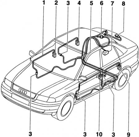
- 1 - hose;
- 2 - switching element of the passenger door next to the driver;
- 3 - connecting piece;
- 4 - door switch element, right rear;
- 5 - part of the outlet under the rear seat;
- 6 - fuel tank door switch element;
- 7 - Double injection pump;
- 8 - trunk lid switching element;
- 9 - door switch element, left rear;
- 10 - driver's door switching element.
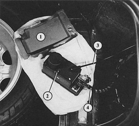
The dual pressure pump (2) for the central locking system is mounted under the right-hand boot trim. Here it is "pulled out" of its foam shell (1). Next you see: the electrical wires (4) and the pressure/vacuum hose (3) to the switching elements.
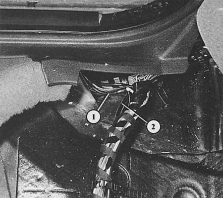
Under the rear seat, the center pressure/vacuum hose branches into a harness to the right doors (1) and a harness to the left doors (2).
Troubleshooting a Pneumatic System
1. To check for leaks in the central lock (symptom: Dual injection pump running too long) the entire system needs to be checked sequentially.
2. Double injection pump: directly at the pump, squeeze the hose with pliers and thus close it tightly. Activate one of the locks.
3. If the dual injection pump operates longer than 3, max. 7 sec. when the central lock is activated, the pump is leaky. Replace it.
4. Switching elements in doors and covers: Clamp all hoses one by one directly next to the switching elements. To do this, remove the corresponding trims (Chapter Body parts). Activate one of the locks each time.
5. The dual injection pump must not operate longer than 3, max 7 s, when the central lock is activated.
6. After disconnecting the defective (non-hermetic) the pump unit operates normally, i.e. less than 3 s. Replace the faulty part.
Tip: To avoid having to remove the entire trim when disconnecting the hoses, you can clamp the hoses at the outlet - first connect them to the right doors, then to the left doors.