



Table of contents: Removal door trim ↓ Disconnecting door parts ↓ Disassembling the outer door handle ↓ Removal the door lock ↓ Removal the outer door handle ↓ Removal the lock drum ↓ Removal window lifters ↓ Removal a window from a door ↓ Adjusting the window in the door ↓ Shockproof slats ↓
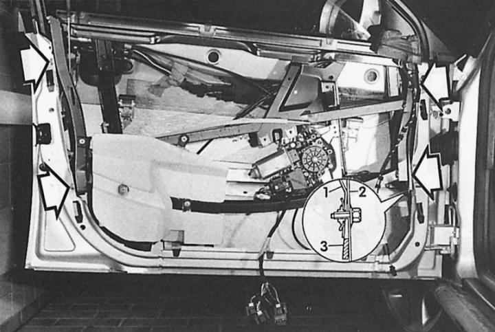
With the door trim removed, the screws (arrows) are visible, which must be loosened in order to separate the two parts of the door. The "magnifying glass" shows the position of the "installation wedge" (3), which is moved more or less between the "door mounting support" (1) and the door base (2) for adjustment.
Removal door trim
Here is described the dismantling of the front door trim. The rear door trim is dismantled in the same way.
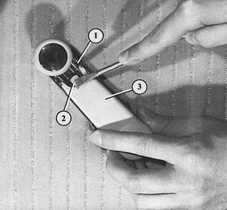
Removing the door trim, stage 1: pressing the fastening lug (2), remove the window lift handle trim (1), then unscrew the handle (3).
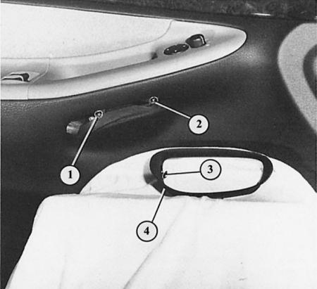
Removing the door trim, step 2: remove the handle cup (4) by loosening the Phillips head screw (3), and unscrew the screws underneath (1 and 2).
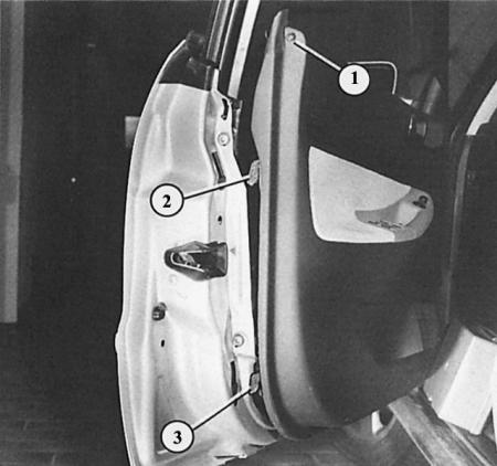
Removing the door trim, stage 3: unscrew the screws (1) from the front side, fold the trim upwards in order to remove the fastening hooks (2 and 3) from the grooves.
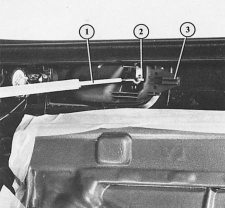
Removing the door trim, stage 4: with the trim removed, hang the door release contact cable (1) from the guide (3) and control lever (2).
1. Remove the window lift crank handle: insert a screwdriver from the crank handle shaft under it and press the fastening tab. Remove the cover to the handle shaft. Unscrew the Phillips-head screw underneath it.
2. Remove the inner door handle cup downwards after loosening the Phillips head screw.
3. Behind the handle, two more Phillips-head screws become accessible. Unscrew them.
4. On the front side of the trim, remove one Phillips-head screw at the front and rear.
5. The internal door lock button remains installed.
6. Now, using your fist, lightly push the door trim upwards from below so that the fasteners on the back of the trim come out of the grooves in the door frame.
7. Remove the trim and move it slightly away from the door.
8. On the back of the door release contact, remove the cable sheath from the guide and hang the cable.
9. Disconnect the plug connectors on the switches and on the speaker.
10. If necessary, carefully remove the insulating film from the back of the door trim. Make sure that it does not tear at the latches and switch contacts.
11. Before installing the trim, insert the intermediate rubber pieces into the holes of the fasteners in the door frame (if they came off during dismantling).
12. To make the clamps move better, lubricate the rubber parts with a small amount of Vaseline or silicone paste.
13. Make sure that the insulation film is carefully inserted on the back of the cladding. It should be inserted into the recess along the perimeter of the cladding.
14. When installing, make sure that the door lock button is correctly inserted into the hole in the trim.
Disconnecting door parts
For example, after slight damage to the metal, it may be necessary to remove the door base from the support of its mounting units. In this case, it is recommended to varnish the new door base before installation. Although after this, you need to work very carefully.
1. Remove the door trim.
2. Dismantle the door as described above and place the outer side on a soft pad (foam, wool blanket).
3. Remove the outer door handle control rod and the lock drum from the mounting clamps. To do this, fold the locking bolt back on the clamps by 90°.
4. Loosen the four mounting screws on the front sides of the door.
5. Remove the door mounting support upwards.
Disassembling the outer door handle
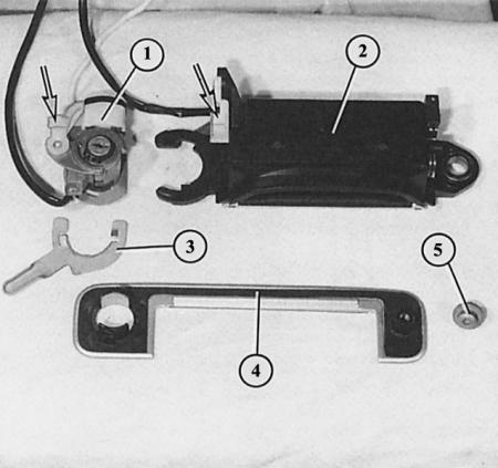
- 1 - lock drum with heating element;
- 2 - door handle;
- 3 - rotary valve;
- 4 - decorative panel;
- 5 - TORX mounting bolt in front.
The arrow shows the spring clamp of the control rod of the opening contact.
Control rod of the lock with the following parts
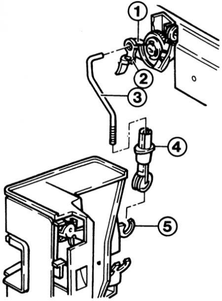
- 1 - drum lock lever;
- 2 - spring clamp;
- 3 - barbell;
- 4 - control spring clamp;
- 5 - lock release lever.
The window regulator is visible from the rear on the functional model:
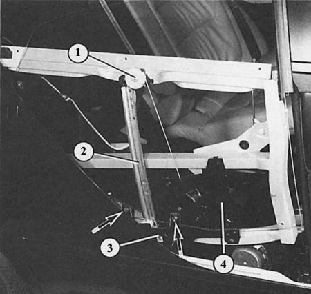
1 – upper guide roller;
2 – window lift guide rail;
3 – glass support;
4 – window lift motor.
Arrows – screw connections of glass/window regulator.
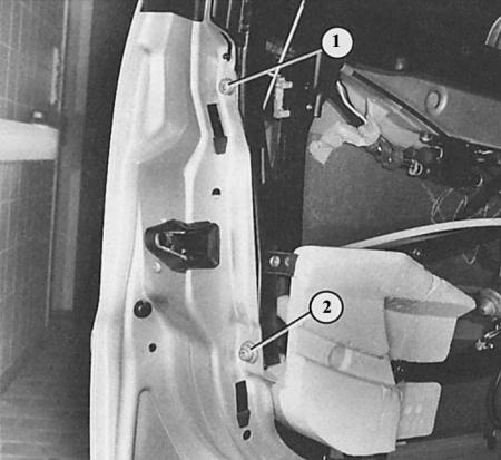
The photo shows the screws (1 and 2) that need to be loosened to separate both door halves.
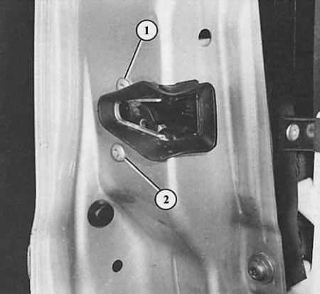
The door lock hangs only on two screws (1 and 2). But the preliminary work on dismantling the lock is significant, because it is necessary to dismantle the "support of the mounting units" from the base of the door.
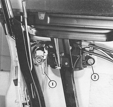
Removing the outer door handle: among other things, you need to fold back the rotary bolt (1) and unscrew the TORX bolt (2).
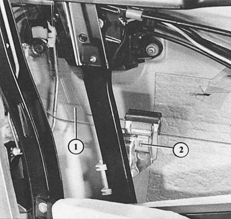
The figure shows the screw connection (2) of the window lifter with the window glass (1) at the rear in the front door frame.
Removal the door lock
1. Remove the door mounting support from its base as described above.
2. Unscrew two 6 mm TORX bolts.
3. Remove the lock.
Tips: In a small series, door locks were installed without a synthetic coating. These locks are dismantled without removing the "mounting unit support" from the door.
When installing a new control rod between the lock cylinder and the door lock, its length must be adjusted. The length can be adjusted by sliding the actuating sleeve back on the hinge part on the lock side of the control rod. The actuating sleeve is then moved forward again, which locks the rod.
Removal the outer door handle
The person who does this work on the installed door must have a calm character and dexterous hands.
1. Front door: Remove the inner door trim.
2. Fold aside the spring clamps of both control rods (they lead to the keystone), hang up the control rods.
3. Using the recess on the inside of the door, unscrew the TORX bolt on the front of the door handle using a T25 key.
4. Feel through the door frame at the height of the lock drum for the small locking lever and fold it back 65° toward the rear edge of the door.
5. Now remove the door handle inside.
6. Remove the lock drum and outer decorative panel outwards, turning the panel slightly as you do so.
7. If necessary, disconnect the wire.
8. Assembly: It is necessary to understand the arrangement of the parts in relation to each other while still dismantled. Otherwise, it is guaranteed that the release lever will not be installed.
9. The release lever is inserted with the handle tilted backwards and folded forward to lock.
10. Rear door handle: removal and installation are similar, but fastening with two TORX screws - without a release lever.
Removal the lock drum
1. Remove the outer door handle.
2. Insert the key into the drum to prevent the lock plates and springs from falling out when the drum is pulled out.
3. Press the locking ring on the rear end of the lock drum.
4. Remove the leash and coil spring, remember their position for subsequent installation.
5. Remove the lock drum from the trim panel.
6. When installing, ensure that the closed tooth on the toothed ring of the gripper fits into the groove between the teeth of the microswitch gear.
7. Lubricate the new lock drum with rust removal and insulation spray.
Removal window lifters
1. Remove the door trim.
2. Remove the door mounting support. The door base remains on the vehicle.
3. Lower the door glass completely.
4. Place the door mounting support on a soft pad.
5. Loosen the window regulator/glass screw connection, lift the glass and remove it.
6. Drill out the four window regulator mounting rivets.
7. The window lifter and crank mechanism are a module and can only be removed or replaced together. This is not the case with the window lifter motor. It can be replaced separately (Chapter Tools and instruments).
8. Installation: rivet the window regulator, placing the lower rivets first.
9. Adjust the window in the door.
Removal a window from a door
The dismantling of the window in the door is described above. In addition, after installation, adjust the glass in the door (next section).
Adjusting the window in the door
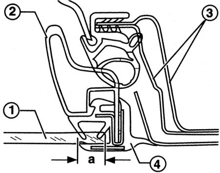
Adjusting the window in the front door: the rear edge of the window (1) of the front door must enter the seal (4) of the support of the door mounting units (2), a = 9 mm. The number "3" indicates the rear door pillar. The same applies to the front edge of the window of the rear door.
The adjustment of the glass in the front and rear doors is carried out in the same way (in mirror image).
1. The glass in the front door should enter the seal with its rear edge (B-pillar) by approximately 9 mm. The same applies to the glass in the rear door as for the front door.
2. At the top and in front, the glass should be parallel to the seal along the entire perimeter. In other words: it should not be skewed in the doorway.
3. If necessary, draw a line along the rear edge of the front glass with a felt-tip pen (or along the front edge of the rear window) at a distance of 9 mm from the edge of the glass.
4. Install the glass – make sure the rubber seal line is parallel.
5. Raise the glass almost to the stop.
6. Now check whether the seal contour and the glass contour are parallel to each other.
7. If not, loosen the glass fastening and adjust the glass so that it is parallel to the seal.
Shockproof slats
The shock-absorbing strips are glued to the door. For dismantling and installation, see chapter earlier.
[This publication is borrowed from the resource: AudiManual.ru]