
Table of contents: Windscreen wiper - removal and… ↓ Windscreen Wiper Arms - Removal and… ↓ Windscreen wiper motor - inspection,… ↓ Rear window cleaner ↓ Rear window wiper motor ↓ Jets - jet adjustment ↓ Heated jets ↓ Headlight washer ↓
Windscreen wiper - removal and installation
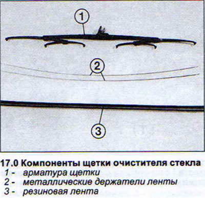
The service life of the rubber band of the windshield wiper blade is approximately six months. The car owner can buy a complete wiper blade assembly for replacement or buy rubber bands and replace the worn ones. In both cases, the blade will have to be removed from the lever (see illustration 17.0).
1. Move the wiper arm away from the glass
2. Press the plastic tab securing the brush to the lever and remove the brush from the lever (see illustration).
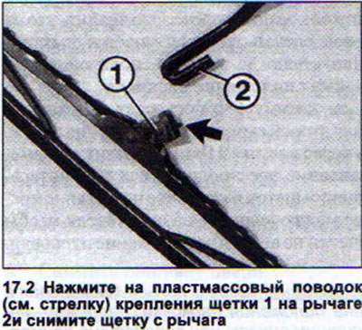
When installing the brush, make sure that the latch securing the brush to the lever is fixed. If the brush fittings are in order, then it is enough to replace the worn tape.
3. Bend the clamps at one end of the brush that hold the rubber band in the reinforcement and pull out the worn band.
4. Place the metal holders on the new rubber band and insert it in place of the old one.
5. Secure the new tape with the retaining clips.
Windscreen Wiper Arms - Removal and Installation
6. Open the hood.
7. Remove the black protective cap from the hex nut of the lever axis and unscrew the nut. Do not forget to remove the lining washer (see illustration).
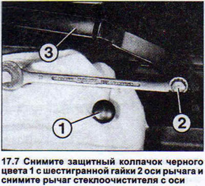
8. Remove the wiper arm from the shaft.
When installing the arms, secure them so that the left wiper blade is 6 cm from the bottom edge of the glass, and the right blade is at the mark at the bottom of the windshield.
9. Make sure the wiper motor is in the park position.
10. Tighten the hex nuts to 16 Nm.
Windscreen wiper motor - inspection, removal and installation
Examination
Power is supplied to the windshield wiper motor when the ignition is on via terminal X of the unloading relay and via the fuse. The purpose of the motor terminals is as follows:
- voltage for the first brush movement speed is supplied to terminal 53.
- power is supplied through terminal 53a to bring the windshield wiper blades to their original position. This means that current flows from this terminal to the electric motor until the blades reach the parking position.
- voltage for the second brush movement speed is supplied to terminal 53b.
- via terminal 31b, the electric motor is braked when the brushes return to their original position after the windshield wiper is turned off, so that the brushes do not go beyond the parking position.
Attention! The brushes must not be blocked outside the parking position, for example, by snow or by the brush freezing to the glass. In this case, when the ignition is turned on, power will be constantly supplied to the motor from terminal 53a and, being unable to move the brushes, it will burn out after a while. Be sure to release the brushes so that they can take the parking position.
If the windshield wiper motor does not work, the cause may be its failure or a broken power wire.
11. Remove the left side trim at the rear of the engine compartment after the wiper arms have been removed.
12. Disconnect the multi-pin connector of the windshield wiper motor.
13. Route two auxiliary wires from the battery to the electric motor. Connect the wire from the positive terminal of the battery to terminal 53 or 53a (a wire with black-gray insulation and a wire with green-yellow insulation are connected to them respectively). Connect the wire from the negative terminal to terminal 31 (a wire with brown insulation is connected to it).
The electric motor should start working, depending on the terminals to which the wires from the battery are connected, with the first or second speed of the brushes. If the electric motor does not start, it is faulty. If it does start, the reason for the failure is a broken wire or a faulty wiper switch.
Removal
14. Turn on the ignition so that the electric motor moves the wiper blades less than 45°.
15. Turn off the ignition and leave the brushes in this position.
16. Disconnect the windshield wiper arms.
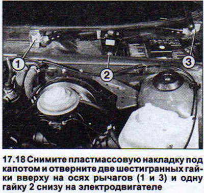
17. Remove the plastic cover under the hood.
18. Unscrew the two hex nuts at the top of the lever axles and one nut at the bottom of the electric motor (see illustration).
19. Disconnect the multi-pin plug of the electric motor.
20. Remove the electric motor together with the rods.
21. Disconnect the rods from the electric motor.
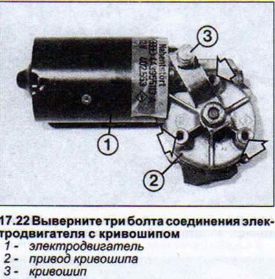
22. Remove the three crank drive bolts. The crank must be moved to provide access to the bolts (see illustration).
23. Apply power to the new motor briefly to get it running.
24. Turn off the power and wait until the electric motor reaches the parking position.
25. Install the electric motor on the console and connect the crank and lever rods. The left lever drive rod is installed on the bottom of the crank, and the right lever rod is installed on top.
26. Tighten the crank, setting it so that line a (see illustration) was shifted by 6° relative to the center of the electric motor axis.
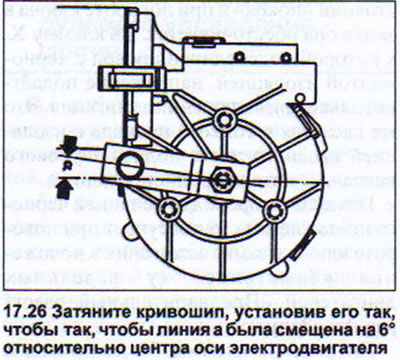
If this position of the crank is not maintained, the lever will initially move downwards when the windshield wiper is turned on.
Attention! Do not tighten the control arm rod nuts too much. They are mounted on plastic bolts.
Rear window cleaner
The rear window wiper is switched on when the steering column switch is moved toward the instrument panel. The windshield washer pump also starts working at the same time. A short press on the switch switches on the interval mode of the windshield wiper. Pressing the switch again switches off the interval mode. Voltage is supplied from terminal 53 to the electric motor, and terminal 53a ensures that the electric motor returns to its original position.
Rear window wiper motor
27. Disconnect the windshield wiper arm.
28. Unscrew the lever axle nut and remove it together with the spacer ring and gasket.
29. Remove the rear door trim.
30. Disconnect the windshield washer hose from the electric motor.
31. Remove the bolts securing the rear window wiper motor holder and remove it together with the motor.
32. Disconnect the multi-pin plug.
33. Disconnect the holder from the electric motor.
When installing a new rear wiper motor, first move it to the park position using the same steps as the windshield wiper motor.
34. Secure the windscreen wiper arm. The wiper blade in the park position should be 40 mm from the lower edge of the rear window.
The windshield washer reservoir is located on the left side of the engine compartment next to the coolant expansion tank. The capacity of the windshield washer reservoir of a car without headlight washers is about 4 liters, and with headlight washers - about 6.5 liters.
First, the appropriate additive is added to the liquid, and then water, so that they mix well.
Unheated windshield washer jets may freeze in severe frosts. To avoid this, it is recommended to increase the volume of antifreeze poured into the windshield washer tank. Adding denatured alcohol to the windshield washer fluid results in the formation of sediment, which clogs the jet holes.
Installing a regular gasoline filter on the windshield washer prevents the nozzle holes from becoming clogged.
Please note! For Avant models, the rear window washer reservoir with a rotating neck is located on the right side of the trunk under the lid.
Jets - jet adjustment
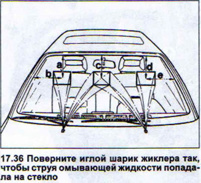
35. Insert the needle into the jet hole. The jet hole is drilled in a ball that can be turned with the needle.
36. Turn the nozzle ball with the needle so that the jet of washer fluid hits the glass. Dimensions for adjusting the jets: a = 20 cm, b = 45 cm, c = 22 cm, d = 48 cm (see illustration).
Heated jets
Directly before the jets, a heating resistor is installed, which depends on the outside air temperature. Power is supplied to this resistor from terminal X when the ignition is turned on. High initial current (0.5 - 0.7 A) ensures rapid defrosting of the jets. To maintain the jet temperature, the current after the jet warm-up phase is reduced to approximately 200 mA. At outside air temperatures below -15°C, the current for maintaining the jet temperature increases to 320 mA.
37. Disconnect the jet plug if necessary to determine the cause of the malfunction.
38. Connect a tester with a test lamp and make sure that the jets are receiving power and that the ground connection is OK. If there is no voltage, then the wire break should be repaired. If power is supplied and the wiring is OK, then the jet should be replaced.
Headlight washer
If the vehicle is equipped with a headlight washer, then when the low or high beam headlights are switched on, when the windshield washer is switched on, two jets of washer fluid are supplied from the headlight washer nozzles to the headlight lens. The operation of the headlight washer is controlled by a relay on the central switch panel. The headlight washer pump is located at the bottom of the washer fluid reservoir. Antifreeze for headlight washing and the corresponding cleaning agent are mixed in the same ratio as for the windshield washer. It goes without saying that the headlight washer nozzles must be adjusted so that the jets of cleaning fluid hit the desired point on the lens. If the quality of cleaning of the headlight lens is unsatisfactory, the jet stream can be adjusted using the VAG 3010A device.
(The original version is on the portal «AudiManual»)