
Table of contents: Instrument panel ↓ Speedometer ↓ Tachometer ↓ Watch ↓ Fuel gauge ↓ Fuel gauge - setting ↓ Coolant temperature gauge ↓ Voltage stabilizer ↓ Additional measuring instruments ↓ Coolant temperature warning light ↓ Coolant temperature warning light ↓ Coolant temperature sensor ↓ Brake system warning light ↓ Oil pressure warning light ↓ Small On-Board Monitoring System… ↓ Direction indicator lights ↓
Instrument panel
1. Remove the steering wheel
2. Remove the steering column trim.
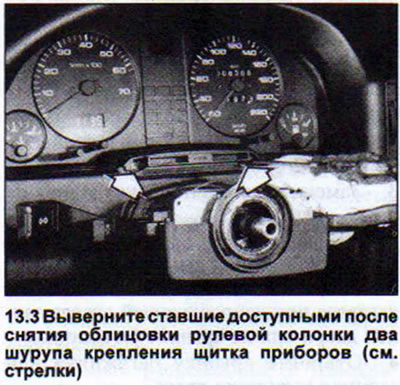
3. Unscrew the two screws that become accessible after removing the steering column trim for the instrument panel (see illustration)
4. Remove the instrument cluster from the panel.
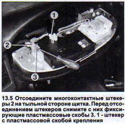
5. Disconnect the multi-pin plugs on the back of the panel. Before disconnecting the plugs, remove the plastic retaining clips from them (see illustration). Depending on the model, the staples can be loosened and removed with a screwdriver or by squeezing the staple lugs.
The following parts can be disconnected from the instrument panel without disassembling the instrument panel:
- control lamps. Their base is combined with the socket. When purchasing bulbs, consider the color of the socket. There are bulbs for 1.1 W, 1.2 W and 2 W. To remove the bulb, simply turn it a quarter turn to the left.
- instrument lighting bulbs.
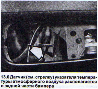
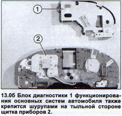
- ambient air temperature indicator. Remove the two Phillips-head screws on the indicator itself and two more on the plug (see 13.0).
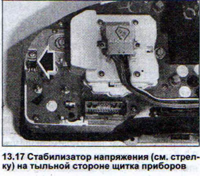
- voltage stabilizer. Unscrew the mounting screw and disconnect the stabilizer.
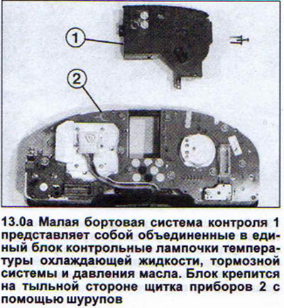
- control lamp block for coolant temperature, brake system and oil pressure (small on-board control system). Remove the mounting screws and detach the unit (see illustration 13.0a). The lights of this control unit are located between the speedometer and tachometer
- diagnostic unit for the functioning of the main vehicle systems (Auto-Check-System). It is disconnected in the same way as the small on-board control system (small control unit) (see illustration 13.0b). This unit is installed upon request instead of the small on-board control system and is an additional vehicle accessory.
- on-board computer. It is disconnected in the same way as the small on-board control system.
- instrument lighting control resistor. Loosen the two hex nuts and remove the resistor by pulling it back (see illustration 13.0v).

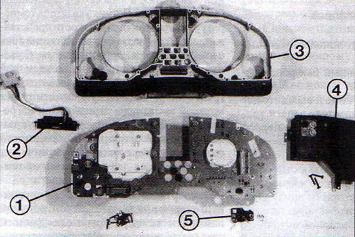
13.0v Instrument cluster parts
1 - printed circuit board
2 - atmospheric air temperature indicator
3 - body
4 - small on-board control system (small control unit)
5 - Instrument cluster backlight resistor
After disassembling the instrument panel, for which it is necessary to first remove the control resistor, the small control unit (or on-board computer), and also unscrew the 11 mounting screws on the back side, access to the following tools and indicators is provided:
- speedometer. Remove the four Phillips-head screws.
- clock with pointer indication. If necessary, first disconnect the coolant temperature gauge.
- tachometer. Remove the three Phillips-head screws.
- clock with electronic indication. Unscrew the two fastening screws and remove the clock by pushing it forward. Release the clock setting pin from the fastening and disconnect.
- fuel gauge and coolant temperature gauge. Unscrew the two nuts and release the gauge from the retaining clips (see illustration 13.0g).
13.0g Disassembled instrument panel
1 - printed circuit board
2 - coolant temperature indicator
3 - tachometer
4 - clock with electronic indication
5 - clock setting pin
Speedometer
The AUDJ 80 cars do not have a conventional speedometer with a flexible shaft from the gearbox. The speedometer used is an electronic measuring device that functions identically to a tachometer. The speedometer, like the tachometer, receives pulses from a sensor installed on the gearbox and reading the wheel speed. The speedometer multiplies the received pulses by a time coefficient, resulting in the vehicle speed. The so-called stepper motor rotates the drive shaft of the mileage counter after receiving a certain number of pulses. The advantages of the electronic speedometer are silent operation and accuracy of readings. In the event of a speedometer failure, the corresponding fuse in the fuse box must first be checked.
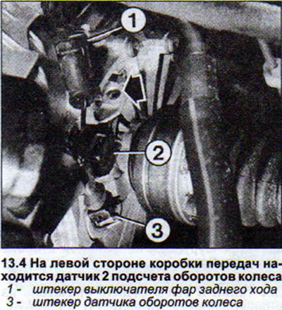
The pulses containing the number of wheel revolutions come from the reed switch sensor located on the left side of the gearbox. The reed switch is a contact group in a sealed casing filled with gas. The sensor is triggered when exposed to a magnetic field. In order for the reed switch to generate pulses corresponding to the wheel speed, the magnetic field acting on it must be interrupted accordingly. For this purpose, a wheel with cutouts is installed in front of the sensor.
1. Raise the front left wheel with a jack.
2. Remove the bracket holding the plug and disconnect the sensor plug.
3. Connect an ohmmeter to both sensor contacts and rotate the front wheel. The ohmmeter should show resistance from 0 to infinity ohms. If this is not the case, the sensor must be replaced.
4. Press the tab holding the sensor, turn the sensor slightly to the right and remove it (see illustration).
When installing a new sensor, make sure the sensor O-ring is seated properly.
Tachometer
The number of revolutions of the crankshaft per minute can be determined by the tachometer. Control pulses are sent to it from the ignition system. These pulses are summed up in the electronic device of the device and transmitted to the mechanism with the pointer. If the tachometer fails, first of all, you should check the corresponding fuse, as well as the wires. The cause of the tachometer malfunction may also be a defect in the printed circuit board of the instrument panel. The tachometer cannot be repaired on your own.
Watch
Only cars with a four-cylinder engine with a power of 66 kW have a clock with an arrow indicator installed on the instrument panel as standard. And only cars with more powerful engines have a tachometer with a small clock with an electronic indicator installed in their place. Both types of clock are quartz.
If the watch does not work, the reason may be a fuse or a broken wire. Watches with electronic indication are not repaired at all, and those with arrow indication - only in specialized workshops.
Fuel gauge
The fuel level in the tank is displayed by a gauge on the instrument panel. The fuel gauge is a voltmeter, to which voltage is supplied when the ignition is on. To keep this voltage constant, a stabilizer is connected to the gauge circuit. The corresponding information about the fuel level in the tank comes from the sensor in the fuel tank. This information is an electrical signal in the form of a resistance value, which can be greater or lesser depending on the amount of fuel in the tank.
If the gauge incorrectly displays the fuel reserve, the cause may be a defective stabilizer or incorrect gauge adjustment. If the gauge does not work at all, the cause of the malfunction may be a defective stabilizer, a defective fuel gauge in the fuel tank, or a failure of the gauge itself.
Fuel gauge - setting
5. Empty the fuel tank completely.
6. Fill the fuel tank with exactly four liters of fuel.
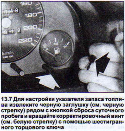
7. Turn on the ignition and wait two minutes. The fuel gauge needle should be positioned on the first long line in the red area. If this does not happen, the gauge can be adjusted using the small adjustment screw on the left side at the bottom of the dashboard. To do this, remove the black plug next to the trip reset button and turn the adjustment screw using a hex key (see illustration).
To check the fuel gauge sensor, remove the trunk floor trim and open the black cover.
8. Disconnect the multi-pin plug located under the cover.
9. Connect the auxiliary wire to the terminal to which the wire with purple and black insulation is connected, and secure this auxiliary wire to the "ground" (-).
10. Turn on the ignition. If the fuel gauge needle on the instrument panel moves completely, the sensor power supply wire and the sensor itself are normal. If the needle does not move, the sensor in the fuel tank is most likely faulty.
If the pointer does not move at all and remains in the "Empty" position, then there may be a wire break, a defect in the pointer stabilizer or the pointer itself. The pointer sensor is most likely in good working order.
Coolant temperature gauge
The coolant temperature gauge works in the same way as the fuel gauge.
Power is supplied to it when the ignition is turned on, and the "ground" (-) is connected to the cylinder block. The coolant temperature gauge sensor is nothing more than a current source with changing resistance. As the coolant temperature increases, the current increases, heating the bimetallic plate on which the pointer is fixed. When heated, the plate deflects the pointer on the instrument panel. Depending on the engine type and configuration, two types of coolant temperature sensors can be installed.
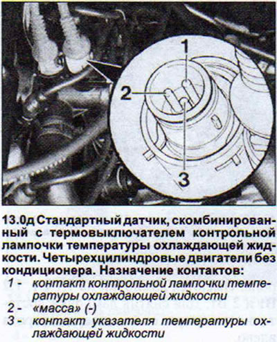
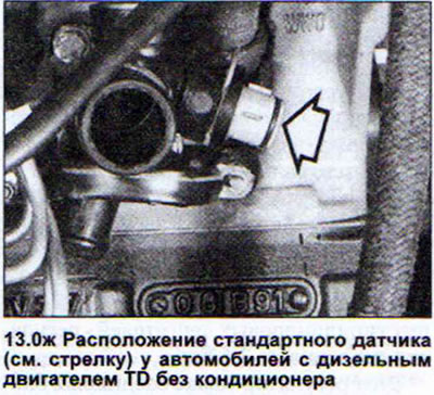
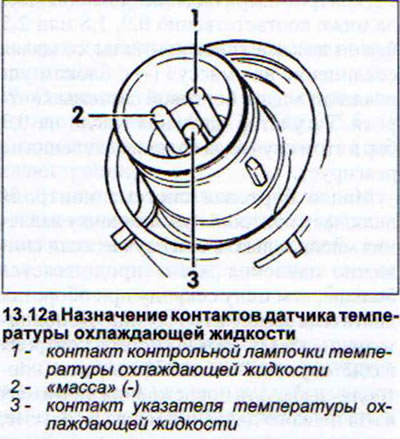
- standard sensor, combined with a thermal switch of the coolant temperature control lamp, which lights up when high values are reached. This sensor is installed on cars with four-cylinder (petrol and diesel) engines without air conditioning (see illustrations 13.0d and 13.0g).
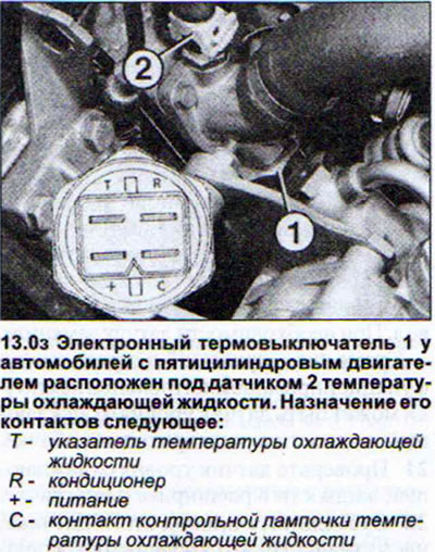
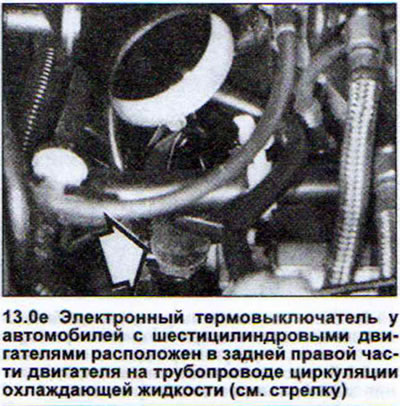
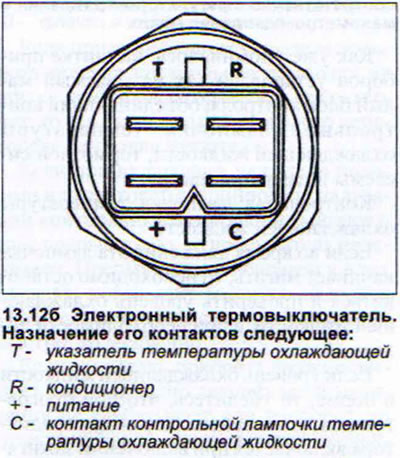
- electronic thermal switch (with additional functions). Installed on vehicles with four, five and six cylinder engines with air conditioning (see illustrations 13.0z and 13.0e).
Attention! When the coolant temperature is high, a flashing control lamp lights up along with the corresponding reading on the gauge. In vehicles with a control unit for the operation of the main vehicle systems installed on the instrument panel, the "Coolant" symbol lights up.
The cause of incorrect display of coolant temperature with simultaneous incorrect indication of fuel reserve may be a defect in the voltage stabilizer on the instrument panel.
If the coolant temperature gauge does not work, this may be caused by a faulty coolant temperature sensor or the gauge itself.
If the indicator correctly displays the current coolant temperature, but the control lamp is flashing, then the cause of such a failure may be a malfunction of the coolant level sensor in the expansion tank.
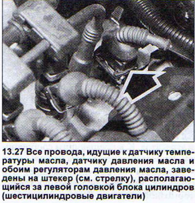
11. Disconnect the multi-pin connector of the coolant temperature sensor in the engine compartment.
12. Secure a separate wire to the plug contact to the coolant temperature gauge on the instrument cluster (a wire with blue-brown insulation is connected to it) and secure it to the "ground" (-) (see illustrations).
13. Turn on the ignition. If the coolant temperature gauge needle starts moving along the scale, the sensor is faulty and must be replaced.
If the pointer arrow still does not move, the cause may be a broken power wire or a malfunction of the pointer itself.
Voltage stabilizer
On the back of the instrument panel there is a small block with three wires. This is the voltage stabilizer. It is designed to maintain a stable voltage supplied to the fuel reserve and coolant temperature indicators. If the arrows of both of these indicators "dance" or the indicators do not work, then the stabilizer may be faulty.
14. Remove the instrument panel.
15. Connect the power wires to the removed panel.
16. Turn on the ignition.
17. Connect a voltmeter to the central and left contacts of the stabilizer, if you look at the panel from behind. The voltmeter should show 9.75-10.25 V. If the voltmeter reading is less than the specified values, then the stabilizer is faulty. If the voltage is not registered at all, then check the power wires. To do this, connect the voltmeter to the central and right contacts of the stabilizer. If the voltmeter does not register the battery voltage, then you need to find a break in the wire (see illustration).
Additional measuring instruments
As an additional option, three measuring instruments can be installed on the central console:
- oil pressure gauge
- oil temperature gauge and
- voltmeter
To remove them, it is necessary to dismantle the center console.
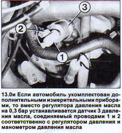
To check the pressure gauge and oil temperature indicator, disconnect the wire from the corresponding sensor of these devices and bring the wire to the "ground" (-). If the arrows of these devices do not deviate, then the wire may be torn or the devices themselves are faulty. Otherwise, the sensor is faulty (see illustration 13.0i).
To check the voltmeter, check the voltage at the voltmeter contacts. If there is voltage, but the voltmeter does not work, then it itself is faulty.
As already mentioned, the instrument panel is equipped with a so-called small control unit, which combines control lights for coolant temperature, brake system and oil pressure.
Coolant temperature warning light
If this light starts to flash while driving, you need to stop and check the coolant level, and top it up if necessary.
If the coolant level is normal, then make sure that when the engine is warm, the radiator fan turns on when the ignition is turned on. If it does not work, despite the fact that the radiator is quite hot, then find and eliminate the cause of the fan failure.
If the radiator fan is functioning normally and the coolant level is also normal, then the reason for the coolant indicator light coming on may be a malfunction of one of the sensors to which the indicator light is connected.
18. Check the bulb itself and the sensors.
Coolant temperature warning light
The coolant temperature indicator light comes on when the ignition is turned on, when the system self-test is performed. If it does not light at this time, check the corresponding fuse. If the fuse is normal, remove the instrument panel, take out the indicator light and check it. If the light is not burnt out and works, replace the entire small control unit on the instrument panel.
Coolant temperature sensor
If the coolant temperature indicator light on the instrument panel flashes when the engine is cold or sufficiently warmed up, the cause may be a faulty coolant temperature sensor.
19. Disconnect the sensor multi-pin plug. The indicator light on the instrument panel should go out.
20. Connect the sensor wire going to the test light to the ground (-). The light should start blinking again (see illustration 13.0d).
This means that the bulb itself is normal, and the cause of the failure is the sensor or a broken wire. Check the sensor and wire. Replace the sensor if necessary.
In addition, the cause of the malfunctioning control lamp may be the coolant level sensor in the expansion tank.
21. Check the coolant level sensor in the expansion tank.
22. Disconnect the wire of this sensor, despite the fact that the coolant level in the tank is normal. If after disconnecting the wire the indicator light stops flashing, then clean the sensor inside the tank or replace the tank together with the sensor.
Brake system warning light
When the ignition is turned on, the control lamp starts to flash, confirming the self-test of the system. When the engine is running, it should go out. If it continues to flash or lights up while driving, then you must immediately check the brake fluid level. It is possible that one of the brake circuits has become depressurized, which should also be felt by the increased travel of the brake pedal.
23. Check the indicator light itself. This check is performed in the same way as checking the coolant temperature indicator light.
If the indicator light flashes when the engine is running, although the brake fluid level in the reservoir is above the minimum mark, disconnect the brake fluid level sensor plug in the reservoir. If the indicator light goes out, the brake fluid level sensor is faulty.
24. Replace the tank together with the sensor.
Oil pressure warning light
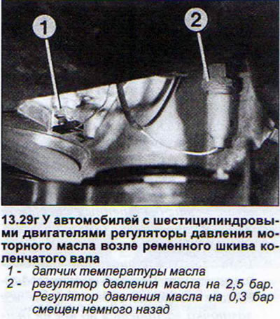
Oil pressure in AUDI 80 cars is controlled by two pressure regulators and a control unit with an acoustic signal. The control unit and the acoustic signal are elements of a small control unit. In a simplified form, oil pressure control occurs as follows.
When the ignition is turned on, the oil pressure indicator lamp is energized. If the oil pressure with the engine off is less than 0.3 bar, the contacts of the 0.3 bar oil pressure regulator close, creating a ground (-) connection with the second contact of the indicator lamp, and the lamp begins to flash.
When the engine starts, the oil pressure begins to increase and the contacts of the 0.3 bar oil pressure regulator open, and the light goes out.
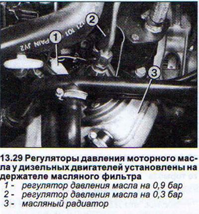
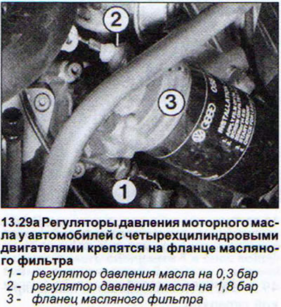
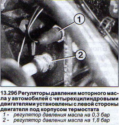
For additional control, vehicles with four- and five-cylinder engines are equipped with a 1.8 bar pressure regulator, while vehicles with diesel engines are equipped with a 0.9 bar pressure regulator. Six-cylinder engines have a 2.5 bar pressure regulator.
This regulator is also connected to the control unit of the small on-board monitoring system. When the oil pressure drops below 0.9, 1.8 or 2.5 bar, respectively, it closes its contacts, creating a connection to the "ground" (-) with the control unit of the small on-board monitoring system. The 0.3 bar oil pressure regulator does not react to the pressure drop in this case.
The small on-board monitoring system switches on the oil pressure warning light only if the drop in oil pressure continues for more than one second at engine speeds above 2100 rpm. In addition, the small on-board monitoring system emits an audible signal. The purpose of this monitoring is to prevent engine damage due to low oil pressure in the system, caused, for example, by a drop in oil level.
To make the oil pressure regulators easier to identify, their insulated ends are painted in different colours.
The 0.3 bar oil pressure regulator is painted brown. In vehicles additionally equipped with an oil pressure gauge, the regulator is replaced by an oil pressure sensor, which is connected to the oil pressure indicator light on the instrument panel (see illustration 13.0i).
The 0.9 bar oil pressure regulator, installed on vehicles with diesel engines, is painted grey.
Pressure regulator 1.8 bar (four and five cylinder engines) it is painted white, and the 2.5 bar pressure regulator for six-cylinder engines is painted red.
If the oil pressure warning light comes on while driving (possibly accompanied by a sound signal), then you need to stop.
25. Turn off the engine.
26. Check the oil level.
27. Disconnect the 0.3 bar oil pressure regulator wire if the oil level is normal and hold the wire so that it does not touch metal (see illustration).
28. Turn on the ignition. If the light still remains on, the wire is shorted to ground (-). This does not pose any danger to the engine.
29. Disconnect the 0.9 bar oil pressure regulator wire (1.8 bar, 2.5 bar) and connect it to the "ground" (-) (see illustrations).
30. Turn on the ignition. If the control lamp still remains lit and the sound signal is heard, then the cause of the malfunction is in the smallest control unit or the sensor wire is broken. This also does not pose any danger to the engine.
If the indicator lamp reacts differently when performing the above checks, then a fault in the engine lubrication system itself cannot be ruled out. The car should be towed to a workshop.
It is also possible that the oil pressure regulator contacts have become loose, which can be eliminated by correcting the regulator fit.
If the oil pressure indicator light does not come on when the ignition is turned on, you must first check the corresponding fuse.
31. Disconnect the 0.3 bar oil pressure regulator wire and connect it to ground (-).
If the indicator light comes on, the oil pressure regulator is faulty. Otherwise, the light bulb is burnt out or the power supply wire is broken.
Small On-Board Monitoring System Control Unit - Check
32. Disconnect the 1.8 bar pressure regulator wire.
33. Secure the wire so that it does not touch any metal.
34. Start the engine and let it run at approximately 2500 rpm. After two seconds, the oil pressure indicator light should come on. A three-time beep should sound. If this does not happen, the small on-board monitoring system is faulty and must be replaced.
If the indicator light comes on but there is no sound signal, then the connection from the generator terminal 61 (D+) is broken.
If the control lamp lights up and a beep sounds when the wire is connected to the oil pressure regulator and the engine is running at about 2500 rpm, then the oil pressure regulator is faulty at 0.9 bar (1.8 or 2.5 bar).
35. Leave the engine running at idle speed and disconnect the wire from the pressure regulator at 0.9 bar respectively (1.8 or 2.5 bar).
36. Secure the wire so that it does not touch metal. If the indicator light and buzzer come on again, the wire from terminal W is broken (diesel engines) or from terminal 1 (gasoline engines) small control system.
37. Install a new pressure regulator that matches your vehicle's engine, using the regulator's color as a guide. Don't forget to install the sealing ring.
38. Tighten the pressure regulator to a torque of 25 Nm, no more.
Direction indicator lights
On the left and right sides at the top of the instrument panel are both indicator lights. They are connected to the indicator lights and therefore flash at the same rate.
If, when the turn signal is on, the green indicator light on the instrument panel lights up and immediately goes out, this is evidence that the indicator light has burned out.
If the indicator or hazard warning lights do not flash in time with the flasher when the turn signal or hazard warning lights are turned on, the flasher is faulty. The flasher is also faulty in cases where the flashing rate of the indicator lights is inconsistent and they flash quickly and slowly.
If the turn signal works normally, but the hazard warning lights do not work, or vice versa, then the cause is a blown fuse or switch.
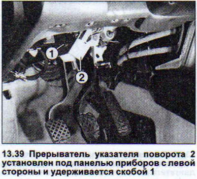
The turn signal flasher is not located on the main relay block, but is fixed under the instrument panel on the left side. This is done specifically so that you can hear the characteristic clicks when the flasher is working.
39. Remove the trim underneath the instrument panel and remove the breaker (see illustration).
40. Disconnect the flasher plug. Driving with a faulty flasher is not always safe. In such cases, we recommend doing the following:
41. Disconnect the breaker.
42. Short-circuit terminals 49 and 49a using a paper clip.
43. Install the breaker back into place.
When the turn signal is turned on, the indicator lights will be constantly lit. The required flashing rhythm of the indicators can be created manually by the steering wheel switch of the turn signal.
The instrument panel contains a number of indicator lights, including:
- a) Battery charge indicator light. This light should not light or flash when the engine is running. If it does not, there is a problem with the power supply system. If the indicator light does not light when the ignition is turned on, it is burnt out or the generator wire is broken.
- b) Trailer direction indicator lamp. It operates in sync with the direction indicators on the towing hitch. If one of the direction indicators on the trailer is faulty, the indicator lamp does not light. The indicator lamp lights up when the hazard warning lights are switched on, even if one of the direction indicator lamps is faulty.
- c) Airbag indicator light. In vehicles equipped with airbags, this indicator light comes on for about 10 seconds when the engine is started. If this does not happen, replace the light. When the engine is running, the light goes out. If the indicator light comes on while driving and does not go out after restarting the engine, this indicates a defect in the airbag unit. The same can be said if the light does not come on at all.
- d) ABS indicator light. In cars equipped with the ABS system, the indicator light comes on when the ignition is turned on. If this does not happen, replace the light. When the engine is running, the light goes out. If the light comes on while driving, the ABS is faulty. In cars manufactured before 6/92, the ABS light comes on when the battery is disconnected.
- d) High beam indicator light. It lights up when you switch to high beam or when you signal with the headlights. However, a lit indicator light does not confirm that the headlight bulb is actually lit. It only confirms that the high beam headlight bulb is receiving power. You must check the headlights yourself.
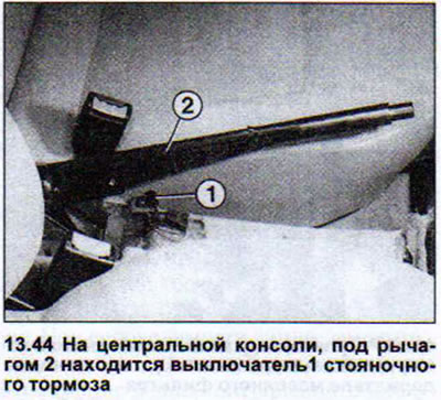
- g) Parking brake indicator light.
If this indicator light does not come on when the parking brake is applied, the fuse must be checked first.
44. Remove and check the bulb. If it is normal, then remove the parking brake switch located under the center console panel and disconnect the wire and connect it to the "ground" (-) (see illustration).
If the indicator light comes on in this case, the switch is faulty.
If the indicator lamp does not go out when the parking brake is released, then perform the check in the same way, but in this case do not connect the switch wire to the "ground" (-). If the lamp goes out, then the switch is faulty or installed incorrectly. If the indicator lamp still lights up, then the power wire is frayed and shorted to the "ground" (-).