
1. Remove the axle shaft.
2. Loosen the clamp securing the cuff on the faulty CV joint and move the cuff onto the shaft. If the cuff is damaged, remove it.
3. Knock the CV joint off the shaft with an aluminum or plastic hammer.
4. Install a new snap ring into the groove on the shaft before installing the new joint.
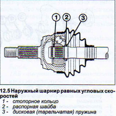
5. Install the disc spring and spacer washer, if any, for the type of CV joint being repaired (see illustration).
6. Tap the joint onto the shaft. The retaining ring should be in place.
7. Fill the joint with grease. A new joint with an external diameter of 81 or 88 mm contains 90 g of molybdenum grease (VW G 6), of which 40 g of this amount is filled into the joint itself, and 50 g into the cuff. A larger amount of grease is needed for joints with an external diameter of 98 mm: 120 g. Of this, 80 g is filled into the joint, and 40 g into the cuff.
If the old CV joint is being installed, then only grease should be added to it.
8. Secure the cuff to the hinge with a clamp.
Inner constant velocity joint - removal and installation
9. Remove the axle shaft.
10. Remove the retaining ring from the end of the shaft that holds the joint to the shaft using two small screwdrivers.
11. Remove the joint from the shaft. If necessary, knock it down with a plastic or aluminum hammer. If the joint does not give in, it must be pressed out using the services of a workshop.
Before installing the CV joint in place, place the cuff on the shaft.
12. Install the disc spring or check its position, if the type of CV joint being repaired has one (see illustration 12.5). The spring should be facing the hinge with its convex side.
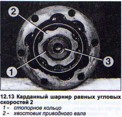
13. Install the hinge on the shaft and secure it with a locking ring. To perform this operation, the shaft should be clamped in a vice, the hinge should be filled with a suitable mandrel or a pipe of a suitable diameter. The hinge will overcome the resistance force of the disk spring and move on the shaft, the locking disk will fit into the groove (see illustration).
14. Fill the joint with grease. A new joint with an outer diameter of 90 or 100 mm contains 90 g of molybdenum grease (VW G 6), of which 40 g of this amount is filled into the joint itself, and 50 g into the cuff. A larger amount of grease is needed for joints with an outer diameter of 108 mm: 120 g. Of this, 35 g is filled into the joint, and 85 g into the cuff.
If the old CV joint is being installed, then only grease should be added to it.
15. Apply VW D3 sealing compound to the contact surface of the CV joint (cuff) to the mounting flange on the gearbox before securing the axle shaft to the flange.
Inner Tripod Joint - Removal and Installation
Tripod joints cannot be removed from the shaft. If the joint fails, it is replaced together with the shaft and the cuff. When replacing the joint, the outer joint on the shaft is dismantled.
If only the protective cuff of the Tripod joint is damaged, then to install a new cuff it is necessary to remove the outer joint. The new cuff for the Tripod is put on from the side of the removed outer joint. The movement of the cuff along the shaft is prevented by the thickening of the shaft. In order not to damage the cuff, lubricate this thickening with a blunt round object (spoon handle) lift the cuff over the thickening.
16. Fill the new Tripod with 140 g of grease G 000 605. When installing the old joint, only add grease to it (see illustration).
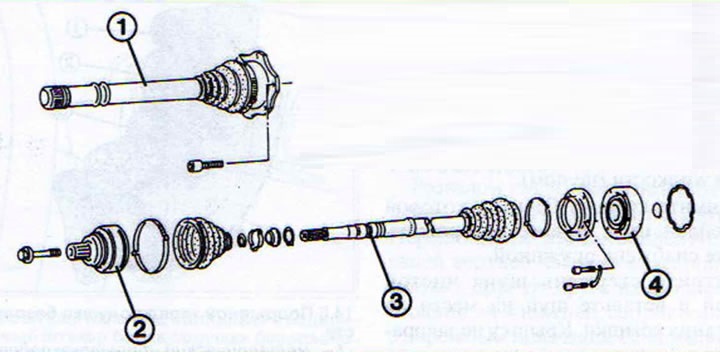
12.16 Constant velocity joint
1 - "Tripod" joint
2 - outer constant velocity cardan joint
3 - drive shaft
4 - internal constant velocity cardan joint
The article is a reprint of material from AUDIMANUAL