Repair Chevrolet Repair Toyota Repair Honda Repair AvtoVAZ Repair Mercedes-Benz Repair BMW Repair Opel
Home  |  Contacts  |  Sitemap  |    
English Русский
Български
Беларускі
Український
Српски
Hrvatski
Română
Polski
Slovenský
Magyar
AudiManual.ru


  • AUDI 80
  • AUDI 100
  • AUDI A3
  • AUDI A4
  • AUDI A6
  • AUDI A8
  • AUDI Q
  • OTHER
  • ARTICLES
B4 (1991-1996) B3 (1986-1991) B3 (1986-1991, petrol) B2 (1979-1986)

Removal and installation the drive shaft (Audi 80 B3)

  • Home
  • Audi 80
  • B3 (1986-1991)
  • Chassis
  • Car suspension
  • Removal and installation the drive shaft
            0
Table of contents: Removal ↓ Installation ↓

Removal


Remove the wheel cap.

Unscrew the hub mounting nut on the drive shaft.

Note: The vehicle must be on the ground.


Remove the washer

Loosen the wheel bolts.

Raise the car.

Remove the wheel.

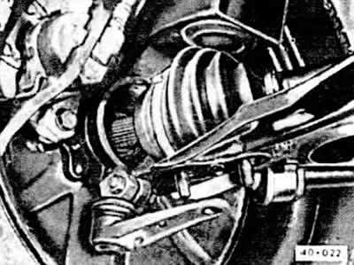
Remove the drive shaft cover.
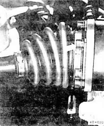
Remove the drive shaft cover.


Remove the internal slotted bolt on the internal joint -arrow-. To do this, you will need a socket for the internal slotted bolt. For example, HAZET 990 Lg-8, for a 100 kW engine; Lg-10.

Press the drive shaft away from the flange.

Power steering vehicles only
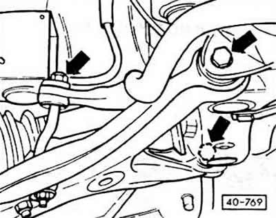


Power steering vehicles only


Unscrew the nut from the connecting rod -arrow- on the left.

Remove the lever and beam mounting bolts.

Press the lever down.

Caution: When removing the drive shaft, ensure that there is free play between the inner constant velocity joint and the gearbox. If necessary, remove the ball joint "23" in Fig. 40-760 from the steering knuckle. To do this, unscrew and remove the tie bolt.


Press the drive shaft out of the hub with a puller. It may not be possible to press the drive shaft out with a regular puller, as it is coated with D6 protective agent. In this case, the drive shaft should be removed with a hydraulic device

Caution: When removing the drive shaft, do not heat the hub under any circumstances, otherwise the hub bearing may be damaged. Be sure to use a removal tool.


Secure the VAG 1389 removal tool to the hub with two bolts.

Press the drive shaft out of the hub using a tool.

Remove the removable device.

Caution: When the drive shaft is removed, the engine of the car must not be started, since the hub bearing may be damaged in the absence of axial load. If necessary, install an external constant velocity joint instead of the drive shaft. For cars with servo control, the lever must be screwed to the beam and to the connecting rod.
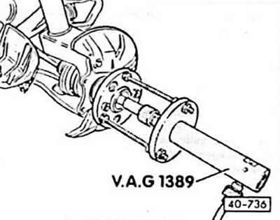

Caution: When the drive shaft is removed, the engine of the car must not be started, since the hub…


Manual transmission vehicles only


Manual transmission vehicles only


Mark the position of the ball joint relative to the lever with a chisel. This will eliminate the need to check and adjust the camber.


Unscrew the ball joint from the lever.

Remove the drive shaft.

Installation


Installation


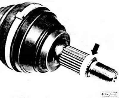
Before installation, clean the gear engagement of the drive shaft and hub with gasoline and remove all traces of protective agent.

Caution: On vehicles with power steering, be careful not to damage the housing when installing the right drive shaft.


Coat the splines of the outer hinge gear for 5 cm with protective agent D6.

Insert the drive shaft into the hub and secure with the old nut. Do not tighten the nut.

Install the drive shaft into the gearbox.

Tighten the inner constant velocity joint internal spline bolts crosswise. Don't forget the shim.

Tightening force:
  • m8 bolts: 45 Nm;
  • m10 bolts (100 kW engine): 80 Nm.

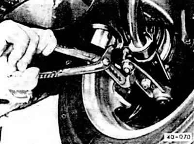
Only vehicles with mechanical steering


Only vehicles with mechanical steering


Use pliers to set the ball joint to the parking position and tighten the new self-locking nuts to 65 Nm.


Caution: When screwing the ball joint to the lever, do not damage the constant velocity joint housing.


Power steering vehicles: Bolt the arm to the beam and connecting rod using new bolts and nuts. Do not tighten the nuts.

If it was removed, insert the ball joint into the steering knuckle and tighten the bolt to 65 Nm.

Screw on the wheel.

Lower the car.

Tighten the wheel bolts to 110 Nm.

Unscrew the nut from the drive shaft and screw on a new self-locking nut with a torque of 265 Nm. Do not forget the washer. Pre-coat the thread with VAG D6 protective agent.

Note: The vehicle must be on the ground.


Vehicles with power steering: Tighten the new self-locking nuts of the control arm on the beam to 65 Nm. Tighten the new self-locking nut of the connecting rod to 20 Nm.

Install the cap.

If necessary, check wheel alignment.
The article was checked by auto expert Elisey Ermolaev
This article is available at russian, bulgarian, belarusian, ukrainian, serbian, croatian, romanian, polish, slovak, hungarian

Share information:
Previous articles
Audi 80 B3: Car suspension
Next articles

Removal and installation the shock absorber/disassembling the…
Shock absorber strut
Removal and installation the shock absorber strut
Front suspension device
Drive shaft
Rear suspension device
Rear shock absorber strut
Checking the shock absorber


Similar articles on other Audi car models:
Drive shaft specifications Audi 100 C3 (1982-1990, diesel)
Clutch and Drive Shaft Specifications Audi A3 Type 8L (1996-2003)
Drive shaft — removal and installation Audi A4 B8 (2007-2015)
Checking the drive shaft protective boot Audi A6 C5 (1997-2004)
Checking the drive shaft protective cover Audi A8 D2 (1994-2002)
Replacing the drive shaft ball bearing Audi Q5 Type 8R (2008-2017)
Tripod Drive Shaft (ANY) Audi A2 (1999-2005)
Link to this page in different formats


Visitor comments

No comments yet


How much will 10 + 16 =


80(B4, 1991-1996) 
  • General information
  • User manual
  • Maintenance
  • Troubleshooting
  • Power unit
  • Engine
  • Cooling system
  • Heating and ventilation
  • Petrol injection
  • Diesel fuel system
  • Fuel system
  • Exhaust systems
  • Ignition system
  • Transmission
  • Clutch
  • Car gearbox
  • Chassis
  • Brake system
  • Suspension and steering wheel
  • Body
  • Body and trim
  • Electrical equipment
  • Electrical system
  • Electrical circuits
 
80(B3, 1986-1991) 
  • General information
  • Repair characteristics
  • Maintenance
  • Power unit
  • Gasoline engine
  • Diesel engine
  • Engine lubrication system
  • Fuel system (gasoline)
  • Injection system (gasoline)
  • Fuel system (diesel)
  • Ignition system
  • Cooling system
  • Heater
  • Exhaust system
  • Transmission
  • Clutch and gearbox
  • Chassis
  • Steering
  • Brake system
  • Car suspension
  • Body
  • Body elements
  • Electrical equipment
  • Power devices
  • Lighting and appliances
  • Electrical circuits
 
80(B3, 1986-1991, petrol) 
  • General information
  • User manual
  • Maintenance
  • Power unit
  • Engine 4-cylinder
  • Engine 5-cylinder
  • Cooling system
  • Fuel and exhaust systems
  • Ignition system
  • Transmission
  • Clutch
  • Mechanical transmission
  • Automatic transmission
  • Drive shafts
  • Chassis
  • Brake system
  • Suspension
  • Steering
  • Body
  • Exterior
  • Interior
  • Electrical equipment
  • Equipment and devices
  • Electrical circuits
 
80(B2, 1979-1986) 
  • General information
  • User manual
  • Power unit
  • Engine FZ
  • Engine EP, YP, YZ, DT, DS, DZ
  • Transmission
  • Clutch
  • 4 speed gearbox
  • 5 speed gearbox
  • Front wheel drive
  • Chassis
  • Front suspension
  • Rear suspension
  • Steering
  • Brake system
  • Electrical equipment
  • Equipment and devices
  • Electrical circuits
 
AudiManual.ru © 2017-2026 · Mobile version · Feedback · Sitemap: EN BG BY UA RS HR RO PL SK HU · Site search · News and articles
80 B2 · 80 B3 petrol · 80 B3 · 80 B4 · 100 C3 diesel · 100 C3 petrol · 100 C3 · 100 C4 petrol · 100 C4 · A3 Type 8L · A4 B5 petrol · A4 B5 · A4 B6 petrol · A4 B6 · A4 B7 · A4 B8 · A6 C4 · A6 C5 · A6 C5 Allroad · A8 D2 · Q5 Type 8R · Q7 Typ 4L · Audi A2 ·
This site uses cookies 🍪. Click the button to accept this fact.