
Table of contents: Disassembly ↓ Assembly ↓
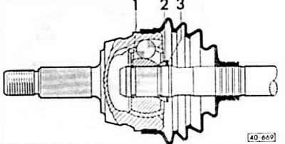
Replace defective seals. To replace the protective covers, the drive shaft must be disassembled. If dirt has gotten into the grease, the joint should be wiped and re-lubricated with G6 grease. Defective balls in the bearing are recognized by beating and noise. In this case, replace the joint as a set.
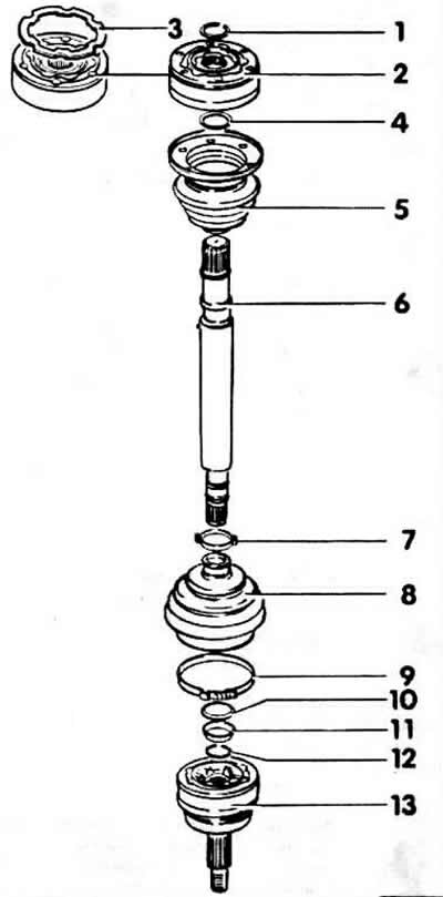
1 retaining ring
2 internal constant velocity joint
External diameter on engines with power:
- 55-66 kW: 90 mm;
- 82-85 kW: 100 mm;
- 100-125 kW: 108 mm.
The constant velocity joint must only be replaced as a set.
3 seal
Available only on engines with a power of 82-125 kW.
4 disc spring
Not available on 100 kW engines.
5 hinge guard with cover
6 shaft
It has different lengths depending on the gearbox design
7 clamp
8 hinge protective cover
9 clamp
10 disc washer
11 spacer washer
12 retaining ring
13 external constant velocity joint
Disassembly
Remove the drive shaft.
Cut and remove the clamps on both hinge housings using side cutters. Slide the protective housings back.
Outer joint: Knock the joint off the drive shaft with a strong blow from a light metal hammer.
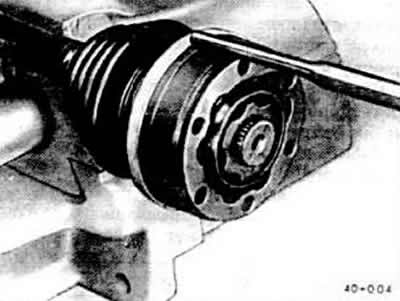
Inner hinge: Use a suitable punch to knock the protective cover off the hinge.
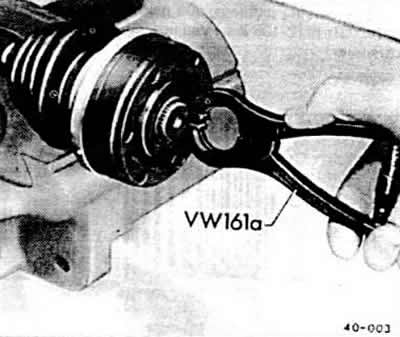
Inner joint: Remove the retaining ring using pliers, for example: VW-161a or HAZET 2525K.
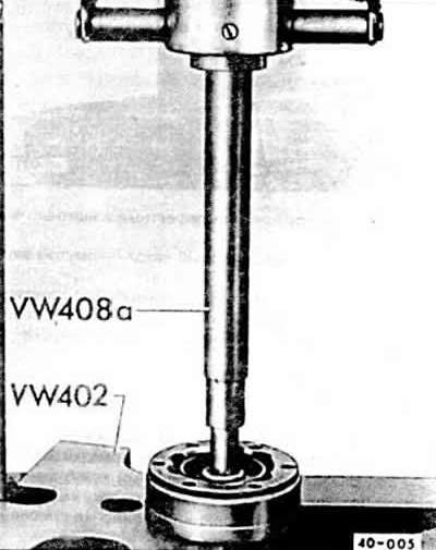
Press the inner joint in with a suitable press, resting it on the inner hub.
Remove the disc spring and protective cover from the shaft.
Note: There are disc springs with and without toothed engagement. When installing, use a new spring of the same design. Cars with a 100 kW (136 hp) engine do not have a disc spring.
Inner joint: for engines with power of 82-100 kW (112-136 hp) remove additional seal.
Assembly
Replace fragile or defective protective covers.
Place the protective cover with the inner joint clamp on the shaft.
Inner joint: install the disc spring on the shaft taking into account the correct position. The large diameter of the disc spring rests against the joint.
Lubricate the inner hinge:
- 55-85 kW engine: 90 g G6 grease, 45 g on each side
- 100 kW engine up to 1 90: 120 g G6 grease
- 100-125 kW engine with 2.90: 250 g grease G000604
If only the hinge cover is being replaced, it is only necessary to add grease to the hinge.
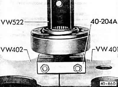
Press the inner hinge into the press until it stops.
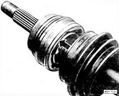
Caution: The chamfer on the inner diameter of the ball ring (teeth) must face the adjacent protrusion on the drive shaft.
Insert the retaining ring into the shaft groove using VW 161a or HAZET 2525K.
Inner joint: coat the clean front side of the joint housing cover with VAG D3 sealant. Tap the cover onto the bearing.
Install the outer bearing cover with clamp and clamp onto the shaft.
Lubricate the outer hinge:
- 55-100 kW engine: 90 g G6 grease, 40 g pressed into constant velocity joint; 50 g evenly insert into the protective cover of the hinge;
- 125 kW engine: 120 g G6 grease, 80 g pressed into constant velocity joint; 40 g evenly insert into the protective cover of the hinge.
If only the casing is being replaced, just add grease to the joint.
Install the disc spring "3" and the spacer washer "2" on the shaft in the correct position. The larger diameter of the disc spring rests against the spacer washer. The spacer washer faces the hinge.
Insert a new retaining ring into the groove of the shaft. Tap the retaining ring onto the shaft with a rubber mallet until it snaps into place in the groove.
Tap the constant velocity joint onto the shaft with a plastic or light metal hammer until the retaining ring snaps into place.
Install the hinge cover in the correct position and tighten the clamp
Note: Often when putting the cover on the hinge body, it is pressed in. Because of this, there is a low pressure in the cover, which forms an internal fold when moving. Therefore, after installing the cover, you should lift the cover at the small diameter with a screwdriver to let in air to equalize the pressure.
The original article is posted on the resource: AUDImanual.ru