
Repair Chevrolet Repair Toyota Repair Honda Repair AvtoVAZ Repair Mercedes-Benz Repair BMW Repair Opel
Home  |  Contacts  |  Sitemap  |    
English Русский
Български
Беларускі
Український
Српски
Hrvatski
Română
Polski
Slovenský
Magyar
AudiManual.ru


  • AUDI 80
  • AUDI 100
  • AUDI A3
  • AUDI A4
  • AUDI A6
  • AUDI A8
  • AUDI Q
  • OTHER
  • ARTICLES
B4 (1991-1996) B3 (1986-1991) B3 (1986-1991, petrol) B2 (1979-1986)

Removal and installation the shock absorber strut (Audi 80 B3)

  • Home
  • Audi 80
  • B3 (1986-1991)
  • Chassis
  • Car suspension
  • Removal and installation the shock absorber strut
            0
Table of contents: Cars from 9/88, starting with… ↓ Cars up to 8/88, up to No.89JA377712 ↓

Cars from 9/88, starting with #89JA377713


The forged steering knuckle and shock absorber strut are screwed together.
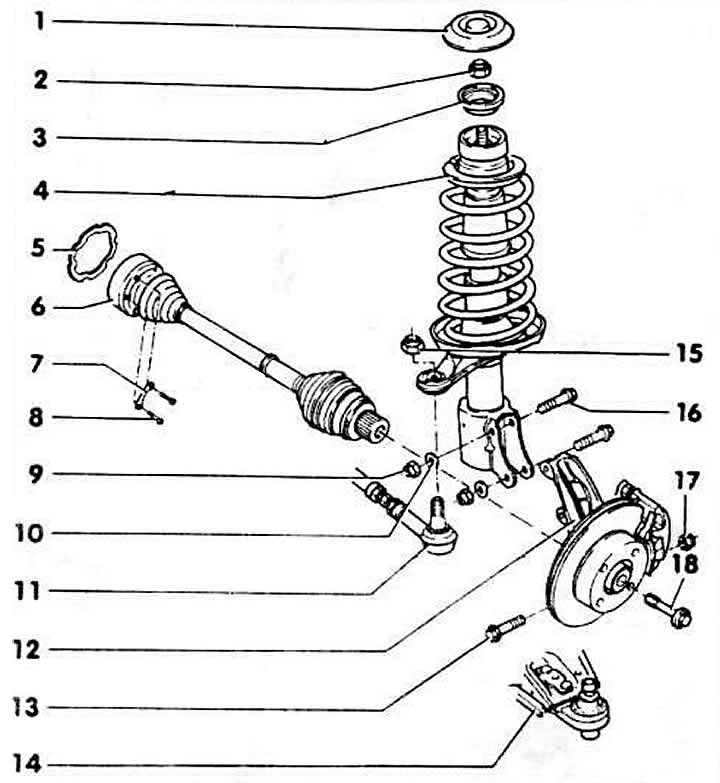
1 lid

1 lid

2 nut, 65 Nm
Self-locking, always replace.

3 emphasis

4 shock absorber strut
To remove the rack, it is not necessary to remove the drive shaft. After installation, measure the geometry of the front suspension.

5 seal
Always replace. Remove the protective film and glue it into the hinge.

6 drive shaft
Since 9.88, no more compound is applied to the splined connections. To remove, unscrew on the flange and also unscrew the hub/drive shaft mounting bolt. When removing, unscrew the steering accordingly.

7 strip-overlay

8 cylinder bolt
Tightening force for bolt M8 - 45 Nm; M10 - 80 Nm.

9 nut, 80 Nm + 90° tighten
Self-locking, always replace.

10 spacer washer

11 steering rod
Remove from the pivot arm using a two-jaw puller.

12 steering knuckle with hub
When pressing out the support journal, do not under any circumstances widen the spline in the steering knuckle (hinge pin seat)

13 hex bolt
It is necessary to replace; the bolt head faces the direction of travel.

14 transverse arm with ball joint
When pressing out the support, do not expand the spline in the steering knuckle. The diameter of the ball joint journal is 19.0 mm.

15 nut, 30 Nm
Self-locking, always replace

16 hex bolt
It must be replaced.

17 nut, 65 Nm
Self-locking. Always replace.

18 hexagon combination bolt 120 Nm + 90° tighten further It must be replaced.


Caution: Loosen or tighten the bolt only when the vehicle is on the ground with its wheels (danger of accident).


Cars up to 8/88, up to No.89JA377712


Removal


Remove the wheel cap.

Unscrew the hub mounting nut on the drive shaft and remove it together with the washer.

Caution: the car must be on the ground. Risk of accident.


Loosen the wheel bolts. Raise the car, remove the wheel.

Note: On vehicles with forged steering knuckles, the shock absorber strut can be unscrewed from the steering knuckle. In this case, it is not necessary to remove the drive shaft. Before removing, mark the position of the bolts with a chisel.


Unscrew the brake caliper.

Remove the brake hose holder and hang the caliper from the body using wire.
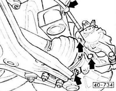
Remove the brake hose holder and hang the caliper from the body using wire.


Caution: Do not disconnect the brake hose from the caliper.


Remove the brake disc.

Remove the ball joint and steering knuckle mounting bolt.
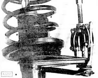
Remove the ball joint and steering knuckle mounting bolt.


Loosen the self-locking nut of the steering tip joint, press the joint with a regular puller, and unscrew the nut.


Unscrew the nut from the connecting rod.

Press the suspension arm down to pull the pivot pin out of the steering knuckle.

For cars with ABS (anti-lock braking system) remove the speed sensor Remove the wires from the holder on the steering knuckle.

For vehicles with mechanical steering, remove the stabilizer.

Remove the drive shaft from the steering knuckle.

Support the front pillar from below with a jack or secure it against tipping over.

Remove the front pillar cover in the engine compartment.
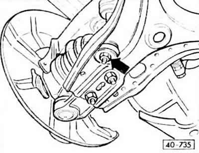
Remove the front pillar cover in the engine compartment.
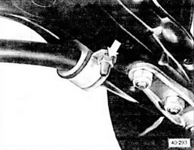

Remove the front pillar cover in the engine compartment.
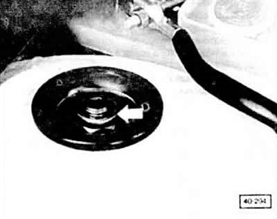

Remove the front pillar cover in the engine compartment.


(Material republished from the website: «audimanual.ru»)
The article was checked by auto expert Elisey Ermolaev
This article is available at russian, bulgarian, belarusian, ukrainian, serbian, croatian, romanian, polish, slovak, hungarian

Share information:
Previous articles
Audi 80 B3: Car suspension
Next articles

Front suspension device
Shock absorber strut
Removal and installation the shock absorber/disassembling the…
Removal and installation the drive shaft
Drive shaft


Similar articles on other Audi car models:
Rear suspension strut/shock absorber — removal and installation Audi 100 C3 (1982-1990, diesel)
Removal and installation the shock absorber strut and wheel… Audi A3 Type 8L (1996-2003)
Removal and installation the front shock absorber strut Audi A4 B6 (2000-2006)
Shock absorber strut Audi A6 C5 (1997-2004)
Shock absorber strut Audi A8 D2 (1994-2002)
Spring strut with upper support, shock absorber fork, upper… Audi Q5 Type 8R (2008-2017)
Link to this page in different formats


Visitor comments

No comments yet


How much will 38 + 47 =


80(B4, 1991-1996) 
  • General information
  • User manual
  • Maintenance
  • Troubleshooting
  • Power unit
  • Engine
  • Cooling system
  • Heating and ventilation
  • Petrol injection
  • Diesel fuel system
  • Fuel system
  • Exhaust systems
  • Ignition system
  • Transmission
  • Clutch
  • Car gearbox
  • Chassis
  • Brake system
  • Suspension and steering wheel
  • Body
  • Body and trim
  • Electrical equipment
  • Electrical system
  • Electrical circuits
 
80(B3, 1986-1991) 
  • General information
  • Repair characteristics
  • Maintenance
  • Power unit
  • Gasoline engine
  • Diesel engine
  • Engine lubrication system
  • Fuel system (gasoline)
  • Injection system (gasoline)
  • Fuel system (diesel)
  • Ignition system
  • Cooling system
  • Heater
  • Exhaust system
  • Transmission
  • Clutch and gearbox
  • Chassis
  • Steering
  • Brake system
  • Car suspension
  • Body
  • Body elements
  • Electrical equipment
  • Power devices
  • Lighting and appliances
  • Electrical circuits
 
80(B3, 1986-1991, petrol) 
  • General information
  • User manual
  • Maintenance
  • Power unit
  • Engine 4-cylinder
  • Engine 5-cylinder
  • Cooling system
  • Fuel and exhaust systems
  • Ignition system
  • Transmission
  • Clutch
  • Mechanical transmission
  • Automatic transmission
  • Drive shafts
  • Chassis
  • Brake system
  • Suspension
  • Steering
  • Body
  • Exterior
  • Interior
  • Electrical equipment
  • Equipment and devices
  • Electrical circuits
 
80(B2, 1979-1986) 
  • General information
  • User manual
  • Power unit
  • Engine FZ
  • Engine EP, YP, YZ, DT, DS, DZ
  • Transmission
  • Clutch
  • 4 speed gearbox
  • 5 speed gearbox
  • Front wheel drive
  • Chassis
  • Front suspension
  • Rear suspension
  • Steering
  • Brake system
  • Electrical equipment
  • Equipment and devices
  • Electrical circuits
 
AudiManual.ru © 2017-2026 · Mobile version · Feedback · Sitemap: EN BG BY UA RS HR RO PL SK HU · Site search · News and articles
80 B2 · 80 B3 petrol · 80 B3 · 80 B4 · 100 C3 diesel · 100 C3 petrol · 100 C3 · 100 C4 petrol · 100 C4 · A3 Type 8L · A4 B5 petrol · A4 B5 · A4 B6 petrol · A4 B6 · A4 B7 · A4 B8 · A6 C4 · A6 C5 · A6 C5 Allroad · A8 D2 · Q5 Type 8R · Q7 Typ 4L · Audi A2 ·
This site uses cookies 🍪. Click the button to accept this fact.