
Attention: Welding and straightening work on load-bearing and wheel-driven parts is prohibited.
The figure shows the suspension of a front-wheel drive vehicle with mechanical steering.
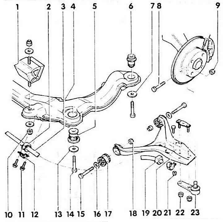
1 - rubber-metal engine mount
Bolted to the engine mount and the powerhead.
2 - rubber bushing of the stabilizer
3 - stabilizer
Installation position: the washer is bent downwards. When installing, the car must stand on its wheels.
4 - beam
Tighten the body mounting bolts in the following sequence:
- 1. left back
- 2. right back
- 3. left front
- 4. right front
5 - front beam support
6 - rear beam support
7 - washer
Replace.
8 - Hex bolt
Replace with bolt head facing in direction of vehicle travel.
9 - nut, 65 Nm
Self-adhesive, always replace.
10 - nut, 40 Nm
Self-locking. Always replace.
11 - bolt, 35 Nm
Self-locking. Always replace.
12 - clamp
When fastening, take into account the correct position of the stabilizer bushing.
13 - washer
Replace.
14 - Hex bolt
Replace. Tightening torque: 35 Nm. then tighten further by ¼ turn.
15 - Hex bolt
Replace.
16 - washer
Replace.
17 - suspension arm bearing
18 - nut, 65 Nm
Self-locking, always replace. When tightening, the car must stand on its wheels.
19 - stabilizer bushing
Insert with talc.
20 - suspension arm
21- nut, 25 Nm
Self-locking. Always replace
22 - nut, 65 Nm
Self-locking, always replace.
23 - ball joint
Mark the installation position by cleaning the ball joint and lever and marking the joint with a felt-tip pen. The bend on the ball joint faces forward in the direction of travel. When pressing out of the steering knuckle, do not spread the spline on the steering knuckle. After installation, adjust the camber. Trunnion diameter = 17 mm. with a forged steering knuckle: diameter = 19 mm.
[Read the original source on the website «AUDIMANUAL.RU»]