
For ease of use, all electrical circuits in the electrical diagrams are arranged vertically and numbered.
The diagrams show the fuse and relay box at the top, bounded by a horizontal line at the bottom. The thin lines above it are the internal connections in the box.
The horizontal lines in the block under numbers 30, 15, X and 31 are the internal connections of the block with power sources and "ground". Circuit 30 is constantly under voltage from the battery, circuit 15 - only when the ignition is on and receives power through the ignition switch. Circuit X is also under voltage when the ignition is on, but when the starter is turned on, it is de-energized. Circuit 31 is connected to "ground".
At the bottom of the diagrams there is a horizontal line that shows the connection to ground.
The numbers in circles located near the intersection of the vertical chains with the horizontal "ground" line indicate the location of the "ground" points on the body.
The number in the white square at the end of the vertical chain shows in which chain you need to look for the continuation of this wire. The colors of the wires on the diagrams correspond to the colors of the wires on the car. The number on each wire indicates the cross-sectional area of the current-carrying core of the wire in square millimeters.
The number in the black square indicates the relay number in the fuse and relay box, the letter in the circle next to the wire indicates a permanent connection of wires.
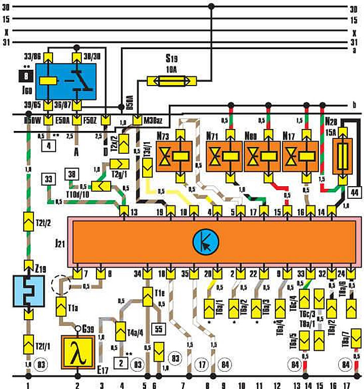
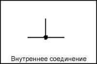
Internal connections (thin lines) – such connections are not wires, but they carry electric current. They make it possible to trace the paths of current flow inside electrical equipment.
Terminal 15 – when the ignition is on, there is battery voltage on it.
Relay Position Number – Indicates the relay, indicates the relay number on the additional relay panel.
The wire cross-section is given in mm².
Element designation – allows you to find the name of an element represented by a graphic symbol in the list.
Wire color - matches the color of the wire in the car.
Contact designations are on the relay, control device and on the board or additional relay panel.
Alphanumeric designation at connection points – determines the position of wires in connectors (M30az).
The numbers in the squares indicate the interruption of the circuit and specify the number of the current path of the continuation of the circuit.
Alphanumeric designation – indicates a detachable connection (T8a/7).
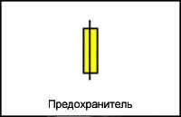
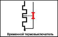
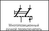
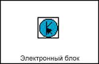
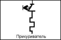
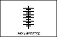
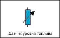
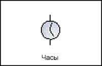
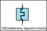
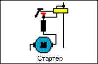
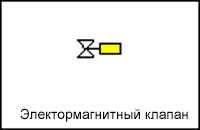
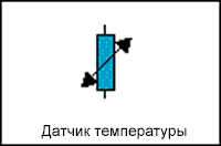
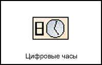
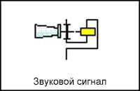
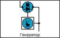
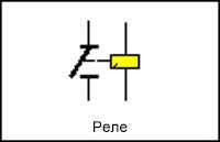
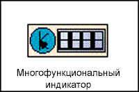
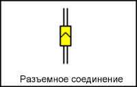
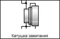
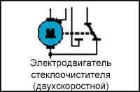
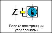
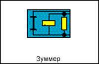
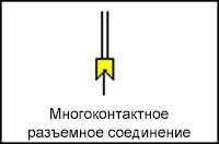
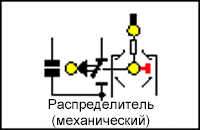
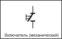
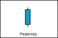
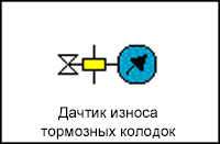
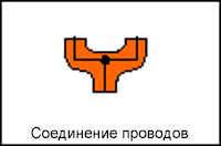
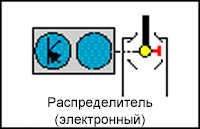
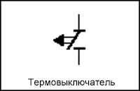
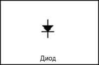
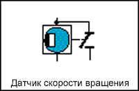
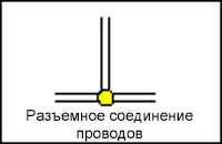
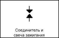
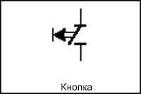
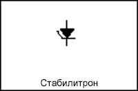
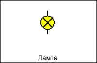
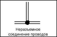
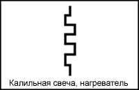
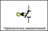
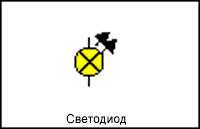
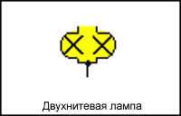
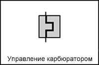
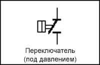
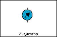
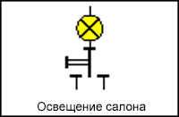
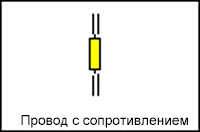
Conventional symbols on electrical diagrams
 |  |  |
 |  |  |
 |  |  |
 |  |  |
 |  |  |
 |  |  |
 |  |  |
 |  |  |
 |  |  |
 |  |  |
 |  |  |
 |  |  |
 |  |  |
 |  |  |
 |  |  |
 |  |  |
 |  |
[Content source: the specified website audimanual.ru]