
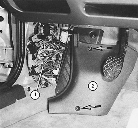
Here the side trim (2) at the driver's feet is unscrewed. The arrows show the mounting screws. Underneath it is a group of connectors (1).
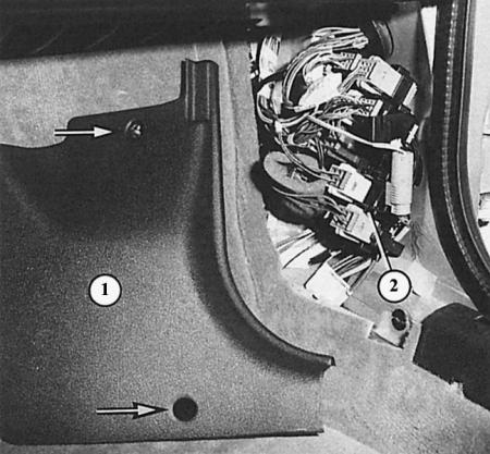
Under the side trim (1) on the passenger side next to the driver there is also a group of connectors (2). The arrows indicate the mounting screws.
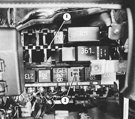
The central switching unit (2) is located in the Audi A4 on the left under the instrument panel. Above it is the "13-position support for additional relays" (1).
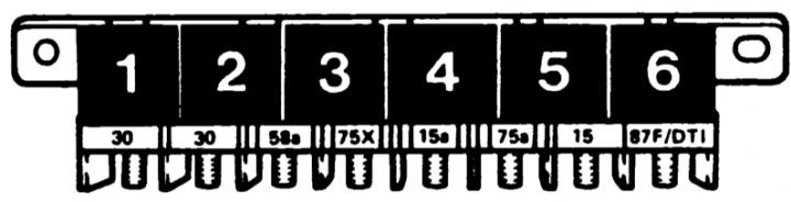
The figure shows the placement of the central switching unit sockets.
Standard terminal designations
The colorful mix of wires in the car is actually very well organized, since many parts of the car's electrical equipment are standardized. The numbers on the various nodes and connectors of the wires, as well as in the electrical diagrams on all German and some foreign cars have the same meaning:
Terminal 15 receives power only when the ignition is on from the ignition switch, while along with the ignition/injection system, those consumers of electricity that should receive current only during the operation of the car are supplied with current. In most cases, the wires to terminals 15 have a black sheath, sometimes with an additional colored stripe for certain current consumers.
Terminal 30 receives direct current from the positive terminal of the battery or from the generator when the engine is running. If the tools are handled carelessly, this can cause short circuits or cause a shower of sparks if the wire connected to the negative terminal of the battery is not removed. These wires, which are always under voltage, are usually red, sometimes with additional colored stripes.
Terminal 49 refers to the system of intermittent and emergency light signals.
Through terminal 53 voltage is supplied to the windshield cleaning system.
From terminal 56 current is supplied to the low-beam headlights via the yellow and yellow-black wires, and to the high-beam headlights via the white and white-black wires.
From terminal 58 supplies power to the front parking lights, as well as to the rear lights and for the license plate light. The main color of the wire sheath is gray, sometimes with an additional color stripe.
Terminal 75 the ignition switch receives current when the ignition key is in the "On" position.
Terminal 31 – ground terminal, by means of which the consumer of electrical energy must be connected to the ground in order to close the electric circuit. The corresponding wires have a brown sheath.
Labeled electrical connectors
In the Audi A4, individual wires are often bundled together in black sheathing, making it difficult to locate a specific wire. In this case, multi-pin connections provide orientation assistance, for which this chapter describes the exact number of wires and their exact locations in the electrical diagrams.
Wires
The cross-section of the wire is selected depending on the power supply needs of each consumer: a control lamp makes do with a wire 0.5 mm² thick, and a starter needs a wire 16 mm² thick. Too thin a wire heats up, and the voltage drops. Then instead of the desired 12 V, for example, on the headlights, only 10 or 9.5 V is supplied – the light becomes dim.