
Table of contents: 12V incandescent lamps ↓ Location of relays and fuses ↓ Main fuse box ↓ Tightening forces of threaded… ↓
Warning: Individual characteristics are also given in the text of the Chapter and, if their implementation is mandatory, are highlighted in bold
12V incandescent lamps
To be able to replace a lamp at any time, it is necessary to always have a box with the most important spare lamps in your car.
| Purpose: | Type | Power, W |
| Low beam | H7 | 55 |
| High beam (without fog lights) | H1 | 55 |
| High beam (with fog lights) | H4 | 55 |
| Front parking light | Glass base | 5 |
| Front turn signal (yellow lamps) | Bayonet | 21 |
| Side turn signal repeater | Glass base | 5 |
| Rear light | Bayonet | 10 |
| Brake light/tail light | Bayonet | 21/5 |
| Rear turn signal | Bayonet | 21 |
| Rear fog light | Bayonet | 21 |
| Reversing light | Bayonet | 21 |
| License plate lighting | Soffit | 5 |
| Additional brake light (10 pcs.) | Glass base | 2.3 |
| Trunk lighting (2 pcs.) | Glass base | 5 |
| Reading light (2 pcs.) | Glass base | 5 |
| Front interior lighting | Soffit | 10 |
| Rear interior lighting | Soffit | 10 |
Location of relays and fuses
The location of the relays and fuses may vary depending on the vehicle equipment and year of manufacture.
The relays are located on the board, behind the left cover in the footwell area, under the instrument panel. In vehicles with a large amount of equipment, there is an additional relay box behind the relay board.
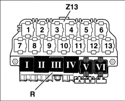
Relay board "R" (relays are shown in dark color)
| relay No | Consumer |
| I | dual tone horn relay |
| II | x-contact unloading relay |
| III | relay automatic windscreen wiper intervals |
| IV | relay fuel pump or glow plug relay |
| V | relay diesel engine injection systems |
| VI | relay fog lights |
| A | fuse electric seat heating |
| B | free |
| C | electric window fuse |
Additional relay box "Z13" above the relay board
| 1 | Horn relay |
| 2 | Relay for control instrument lamps rear |
| 3 | Relay for control instrument lamps rear |
| 4 | Mirror Cover Control Device |
| 5 | Mirror Cover Control Device |
| 6 | Telephone Isolation Relay |
| 7 | Free |
| 8 | Free |
| 9 | Free |
| 10 | Free |
| 11 | Starter and light blocking relay reverse |
| 12 | Headlight Washer Relay |
| 13 | Fan free running relay radiator (air conditioner) |
Main fuse box
Main fuse box fuse location
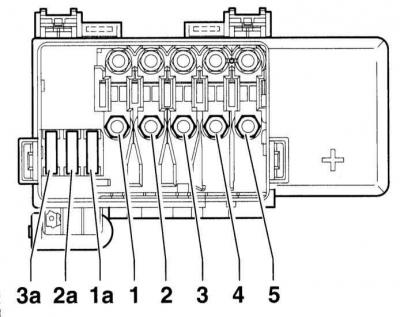
- 1 S131 Glow plug heater (diesel engine)
- 2 S132 Engine management system
- 3 S133 Coolant fan 2
- 4 S134 Salon
- 5 S138 Generator
- 1a S162 ABS (hydraulic pump)
- 2a S163 ABS (valves)
- 3a S164 Coolant fan
Colour coding of fuses
| Current, A | Fuse color |
| 5 | Beige |
| 7.5 | Brown |
| 10 | Red |
| 15 | Blue |
| 20 | Yellow |
| 25 | White |
| 30 | Green |
Location of fuses in the box
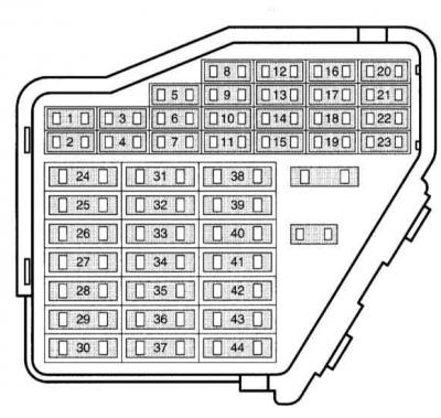
The location of the fuses depends on the vehicle's equipment and year of manufacture. The location of the fuses is shown on the fuse box cover.
| № | Current, A | Fuse |
| 1 | 10 | Heated windshield washer nozzles, heated exterior mirror |
| 2 | 10 | Direction indicators |
| 3 | 5 | Glove compartment lighting |
| 4 | 5 | License plate lighting |
| 5 | 7.5 | Electrical comfort equipment, speed control, heated seats, air conditioner |
| 6 | 5 | Single lock |
| 7 | 10 | Rear lights move |
| 8 | 5 | Phone/Telematics |
| 9 | 5 | Control device ABS |
| 10 | 10 | Control engine: gasoline engine |
| 11 | 5 | Instrument cluster unit, selector lock solenoid for AT |
| 12 | 7.5 | Power supply self-diagnosis, telephone, navigation system |
| 13 | 10 | Brake lights |
| 14 | 10 | Interior lighting, single lock |
| 5 | Salon light | |
| 15 | 5 | Instrument cluster unit, AT, auto-dimming interior mirror |
| 16 | 10 | Electromagnetic clutch, radiator cooling fan runout, windshield washer |
| 17 | 7.5 | Heated door lock |
| 18 | 10 | High beam right |
| 19 | 10 | High beam left |
| 20 | 10 | Low beam right, range adjustment sveta |
| 21 | 10 | Near left light |
| 22 | 5 | Overall dimensions and the right parking light |
| 23 | 5 | Overall dimensions and the left parking light |
| 24 | 20 | Wiper, water pump |
| 25 | 25 | Fan fresh air, circulation ventilation, air conditioning |
| 26 | 20 | Rear window heating, mirror heating |
| 27 | 10 | Rear wiper glass |
| 28 | 15 | Fuel pump |
| 29 | 15 | Control engine: gasoline engine |
| 10 | Engine control: diesel engine | |
| 30 | 20 | Sliding roof panel |
| 31 | 20 | Automatic transmission |
| 32 | 10 | Engine control: petrol engine |
| 30 | Engine control: diesel engine | |
| 33 | 20 | Headlight cleaner |
| 34 | 10 | Engine management |
| 35 | 30 | Trailer socket (positive long term plus) |
| 36 | 15 | Fog lamp and fog light |
| 37 | 10 | S-contact, terminal 86 (radio) |
| 38 | 15 | Trunk lighting, single lock, power windows |
| 39 | 15 | Emergency alarm system |
| 40 | 20 | Sound signal |
| 41 | 15 | Cigarette lighter |
| 42 | 25 | Radio |
| 43 | 10 | Engine management |
| 44 | 15 | Seat heating |
Warning: Fuses in the fuse box are designated starting from location 23 on the diagram as number 223, fuse 24 as number 224, etc.
Other fuses and relay locations are shown in the Electrical Diagrams section.
Tightening forces of threaded connections
Tightening torques for fasteners are also given in the text of the Chapter and in some illustrations*.
* Tightening torques highlighted in bold in the text must be strictly observed; efforts not in bold are only approximate
Cars of this brand are equipped with a 12 V electrical system with grounding on the negative pole. Power for all lighting devices and electrical units is provided by a lead-acid battery, recharged by an alternator.
This Chapter describes the maintenance and repair procedures for certain components of the on-board electrical system, which include, in addition to the specific components discussed below, all lighting fixtures and electrical accessories not directly related to the engine. In addition, diagnostic procedures for general electrical faults are discussed.
Warning: When performing any repair or maintenance work on electrical system components, it is imperative to first disconnect the negative battery cable to avoid electrical shock and/or fire.