



Table of contents: Reference dimensions for checking… ↓ Reference dimensions for checking… ↓ AUDI 100 with a body "sedan" and… ↓ AUDI 100 saloon since 1982 model year ↓ AUDI 100 sedan 1983-1991 model years ↓ AUDI 100 wagon 1983-1991 model years ↓ Explanations for the body control… ↓
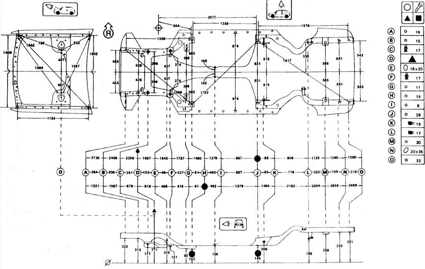
Reference dimensions for checking the body control points of the AUDI 100 1983-1987 model years
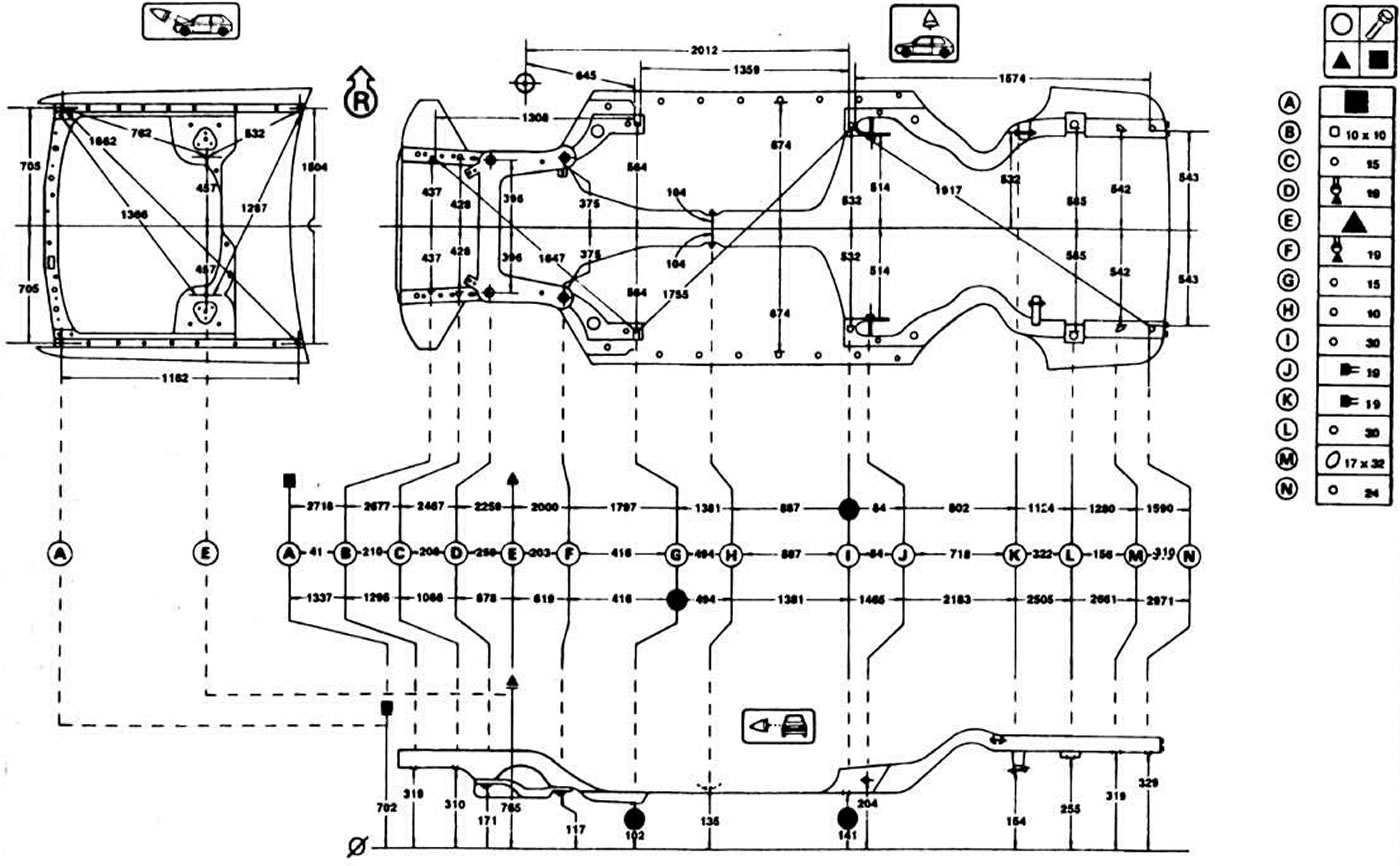
Reference dimensions for checking the body control points of the AUDI 100 since the 1987 model year
AUDI 100 with a body "sedan" and "station wagon" 1982-1991 model years
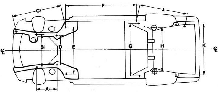
AUDI 100 saloon since 1982 model year
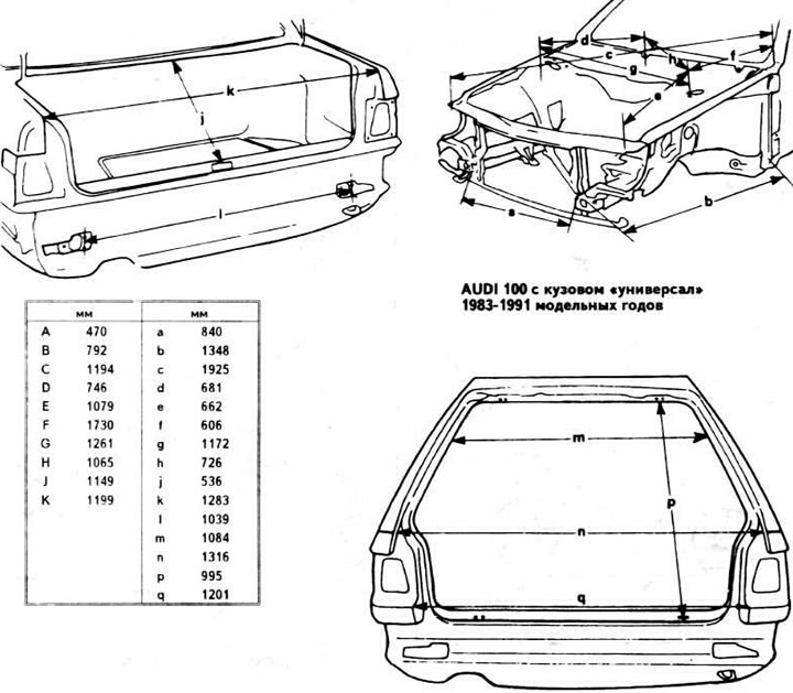
AUDI 100 sedan 1983-1991 model years
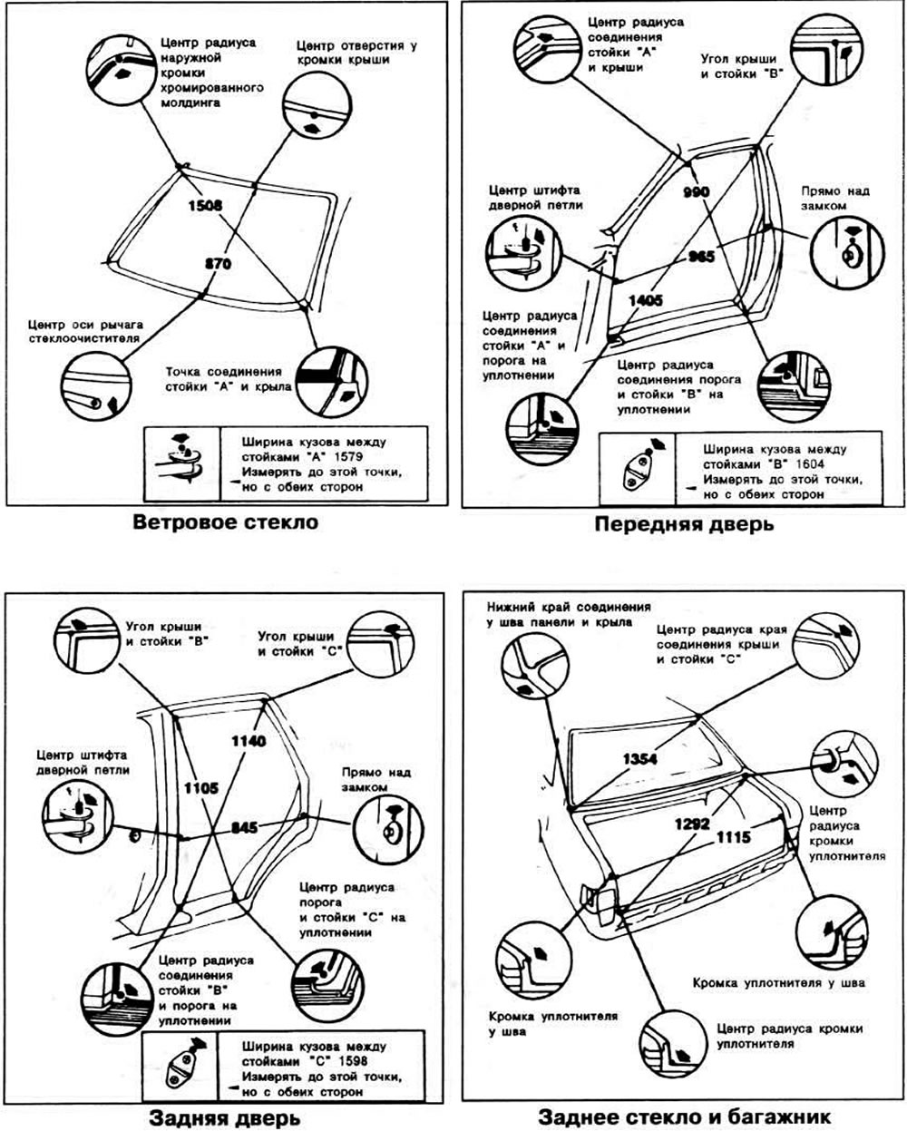
AUDI 100 wagon 1983-1991 model years
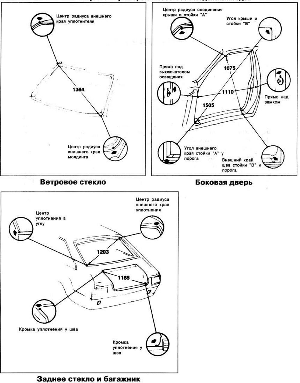
Explanations for the body control point diagrams
The body control points are marked with the letters A, B, C, etc. Each diagram has a table in which the dimensions of the corresponding holes and bolts are indicated opposite the control point.
In the top diagram, the diagonal and width measurements between the control points are calculated to the nearest edge of the hole. The measurements between bolts, nuts, studs, permanent plugs and rivets are measured between their centers.
In the upper diagram, all dimensions, except for the width dimensions, are measured between the control points. To check them, it is necessary to use a measuring rod, the ends of which should be extended to the same length. For the same purposes, if the body parts do not interfere with the measurement, a metal tape measure can be used.
In the diagram of the engine compartment check points, all dimensions, except for the dimensions between the suspension element fastening parts in width, are given between the check points.
Dimensions are in millimetres and rounded. The tolerance is +5 mm. The body elements contain callouts for each fragment, which show the exact location of the measurement point, as well as instructions for measurement.
[Read the original source on the website: audimanual]