



Removal
1. Mark the position of the front wheels on the hub. This will allow you to install the balanced wheel in its original position during assembly.
2. Loosen the wheel mounting bolts. The vehicle must be standing on its wheels when performing this operation.
3. Place the front of the car on jack stands, unscrew the bolts and remove the front wheels.
Caution! If the brake pads are to be reinstalled for further use, they must be marked before removal. Switching the pads from the right wheel to the left and vice versa or switching the outer and inner pads is not allowed. Be sure to replace all the brake pad linings on the front wheels, even if only one of them has reached the wear limit.
4. Remove the protective caps from both caliper guide pins(see arrows in the illustration).
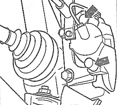
2.4 Remove the protective caps from both caliper guide pins (see arrows)
5. Remove the brake shoe pressure spring by prying it off with a screwdriver (see illustration).
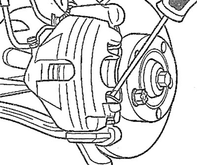
2.5. Remove the brake shoe pressure spring by prying it up with a screwdriver
6. Unscrew the guide pins using a socket wrench (see illustration).
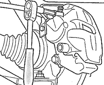
2.6. Unscrew the guide pins using a socket wrench
7. Remove the caliper and secure it to the body with wire without disconnecting the brake hose from it.
Caution! The caliper must be secured so that it does not sag and does not stretch or twist the connected brake hose with its weight.
8. Remove the outer brake shoe from the guide.
9. Remove the inner brake shoe from the caliper by disconnecting it from the wheel cylinder. Installation
Caution! When the brake pads are removed, do not press the brake pedal. In this case, pressing the pedal will force the piston out of the brake cylinder. If the piston does come out of the cylinder, remove the caliper and deliver it and the piston to a workshop for repair.
10. Clean the brake pad seating and guide surfaces in the caliper and guide with a rag soaked in alcohol. Do not use solvents containing mineral oils or tools with sharp edges. Particular attention should be paid to ensuring that no residue of the protective film remains on the mating surfaces of the brake linings.
Caution: Use only alcohol to clean the brake mechanism.
11. Before installing the pads, check the brake disc for ribbing by running your hand over it.
12. Measure the thickness of the brake disc (see the relevant chapter) and replace both disks if necessary.
13. Check the condition of the brake cylinder piston protective cap. Replace a damaged or cracked cap immediately, because dirt penetrating through a damaged cap quickly leads to depressurization of the caliper. In this case, the brake caliper must be removed and disassembled (the work is carried out in the workshop).
14. Press the brake cylinder piston as far as possible into the cylinder using a special pressing device. You can also use a wooden rod made of hard wood (hammer handle), but do not distort the piston or damage its surface and its dust cap (see illustration).
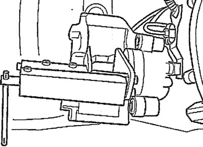
2.14. Press the brake cylinder piston as far as possible into the cylinder using a special pressing device. You can also use a wooden rod made of hard wood (hammer handle), but do not distort the piston or damage its surface and its dust cap
Caution! When the piston is pressed, brake fluid is squeezed out of the wheel brake cylinder into the expansion tank. Monitor the brake fluid level in the expansion tank and remove it if necessary to prevent it from spilling out.
Attention! To extract brake fluid from the expansion tank, use a siphon or a plastic bottle that is not destroyed by the brake fluid. Do not use regular drinking water bottles! Brake fluid is poisonous and should never be sucked out by mouth through a hose. Use a siphon. And after replacing the brake pads, the brake fluid level in the tank should not exceed the maximum mark, because it expands when heated. The leaking brake fluid flows down the master cylinder, destroys its protective varnish layer and causes corrosion.
15. Secure the inner brake shoe to the wheel cylinder using the pressure spring (see left arrow in illustration).
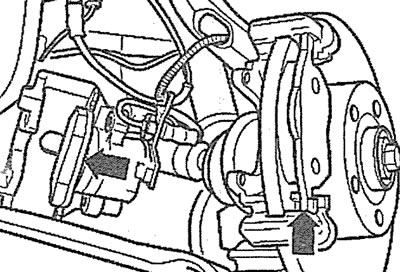
2.15. Secure the inner brake shoe to the wheel cylinder by inserting the retaining spring on the shoe into the cylinder (see left arrow)
Attention! The inner brake shoe is marked with an arrow, which when installing the shoe should point forward in the direction of the vehicle's travel. If the shoe is installed incorrectly, noise may occur while driving.
16. Remove the protective film from the back of the outer brake pad.
17. Install the outer brake shoe (see right arrow in illustration 2.15) onto the guide. Be careful not to damage the adhesive layer on the support plate.
18. Secure the caliper by screwing in both guide pins and tightening them to 25 Nm.
19. Install protective caps on the heads of the caliper guide pins.
20. Install the brake shoe pressure spring into the holes on the caliper.
Caution! After both ends of the spring are secured in the holes, the spring should be placed under the shoe guide. If the spring is not installed correctly, the outer brake shoe will not self-install as it wears, which will lead to an increase in the brake pedal travel.
21. Install the front wheels in accordance with the marks made during removal. Do not lubricate the wheel bolts, and replace rusty ones with new ones.
22. Screw in the wheel mounting bolts and lower the vehicle.
23. Tighten the wheel mounting bolts to a torque of 120 Nm, acting in a crisscross pattern.
Attention! Press the brake pedal several times until you feel a strong resistance to pressing. When you do this, the brake pads are centered and they automatically set themselves to the working position.
24. Check the brake fluid level in the expansion tank. If necessary, top up the fluid to the maximum mark.
Attention! Make sure that:
- brake hoses are securely connected and fixed in the holders;
- the brake fluid bleed nipples are screwed in;
- there is sufficient brake fluid in the expansion tank.
25. Perform a brake system leak test by starting the engine.
To do this, press the brake pedal with a force of 200-300 N (20-30 kg) and hold it for about 10 seconds. The pressure in the system and, accordingly, the resistance of the brake pedal, should not decrease. Check all connections for leaks.
26. Carefully break in the new brake pads. To do this, brake several times, bringing the speed from about 80 km/h to 40 km/h and pressing the brake pedal lightly. Let the brakes cool down in between.
Attention! New brake pads must be worked in. Therefore, until the mileage of at least 200 km with new brake pads, avoid unnecessary braking until the car comes to a complete stop.