



Technical data of the brake system
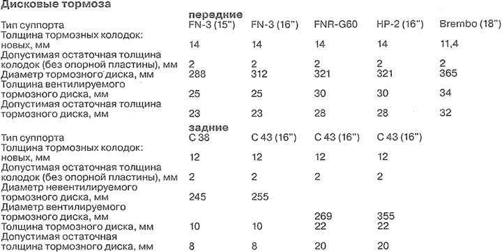
The brake system consists of a brake master cylinder, a brake booster, and rear and front disc brakes. The hydraulic brake system is divided into two circuits that operate diagonally. One hydraulic circuit acts on the front right and rear left wheels, and the other on the front left and rear right. This ensures that the vehicle stops with sufficient efficiency in the event of, for example, a leak in one of the brake system circuits. The pressure for both circuits is created by a dual brake master cylinder when the brake pedal is pressed.
The expansion tank with brake fluid is located in the engine compartment above the main brake cylinder and is closed with a lid. It supplies the entire brake system with brake fluid.
The brake booster in cars with a gasoline engine uses the vacuum in the intake manifold and increases the applied force when the brake pedal is pressed. Since the diesel engine has almost no vacuum in the intake manifold, cars with a diesel engine are equipped with a special brake booster vacuum pump. The vacuum pump in cars with a 4-cylinder diesel engine is mounted on the cylinder block on the left side and is driven by the intermediate shaft. In cars with a 6-cylinder diesel engine, the vacuum pump is installed on the end face of the left cylinder block head.
Disc brakes are equipped with a so-called floating brake caliper, formed by a support and a wheel cylinder, which are tightened with bolts. In the cavity of the wheel cylinder, one piston is installed, providing sufficient pressure of both brake pads to the brake disc.
The parking brake acts via a cable drive on the rear wheel brake mechanisms.
Attention! Work on the brake system requires careful observance of cleanliness and precision. If the necessary experience is not available, it is better to entrust such work to a specialized workshop.
AUDI ALLROAD vehicles are also equipped with systems that increase stability and active safety. Such systems are ABS/EBV/EDS/ASR/ESP. It is possible to equip with ABS/ESP from Bosch version 5.7 or 5.3 (see illustrations 1.0 and 1.0a).
The anti-lock braking system ABS prevents the wheels from locking during sudden braking. Thanks to this, the car remains controllable even when braking to a complete stop.
The Electronic Brake-Force Distributor (EBV) redistributes the braking force between the rear wheels using the ABS hydraulics. The electronic brake-force distributor is more "sensitive" than the mechanical one, and, accordingly, its range of capabilities is much wider.
When driving straight, the rear brakes are fully applied when braking. In order to ensure vehicle stability when braking on turns, it is necessary to reduce the braking effect experienced by the rear wheels. Based on the information transmitted by the ABS sensors about the rotation speed of the wheels, the electronic distributor recognizes whether the vehicle is moving straight or turning. When driving on a turn, the braking force on the rear wheels is reduced, which provides them with maximum lateral force.
Electronic differential lock (EDS) brakes the slipping wheel and transfers traction to the wheel that is not slipping and has a stronger grip on the ground or road surface.
EDS is activated immediately at the start of movement and is automatically deactivated when the car reaches a speed of about 40 kilometers per hour. EDS does not affect the dynamic properties of the car and does not reduce the comfort of driving during acceleration.
The Electronic Stability Program (ESP) reduces the risk of skidding by automatically adjusting the braking force. If, for example, the rear of the car starts to skid, the ABS hydraulics brake the front wheel on the outside of the turn, thereby stabilizing the stability of the car.
Traction control system (TCS) reduces the torque transmitted to the drive wheels if they slip.
The interlock in the ABS/EBV/EDS/ASR/ESP control unit ensures automatic system shutdown in the event of a malfunction, such as a power cable break or battery voltage drop below 10 V. The shutdown of the corresponding system is signaled by the corresponding indicator light on the instrument panel. The normal braking system remains in effect when ABS/EBV/EDS/ASR/ESP is switched off. In this case, the car behaves as if it were not equipped with the ABS system.
Attention! If the ABS and brake system warning lights come on while driving, remember that in the event of sudden braking, the rear wheels may lock due to the lack of braking force regulation.
If, while driving, one or more warning lights concerning the above-mentioned systems light up on the instrument panel, it is recommended to do the following:
1. Stop, turn off the engine, and then start it again.
2. Check the battery voltage. If the battery voltage is less than 10.5 V, charge the battery.
Attention! If the warning lights come on at the start of movement and go out after some time, this indicates that the battery voltage was too low, but then increased during movement as a result of recharging from the generator.
3. Check that the wire terminals are securely fastened to the battery terminals.
4. Raise the vehicle on jack stands and remove the wheels. Check the wheel speed sensor wires for external damage (grinding). Further checking of ABS/EBV/EDS/ASR/ESP should be performed in a workshop.
Attention! When working with electric welding, the plug of the ABS/EBV/EDS/ASR/ESP electronic unit must be disconnected. Disconnect the plug only when the ignition is switched off. When performing paintwork, the control unit can be exposed to short-term high temperatures of no more than +95°C and long-term (maximum within 2 hours) temperatures not higher than +85°C.
Content source: the specified website AudiManual.ru