
Table of contents: Removal ↓ Installation ↓
The underside of the outer brake pad, which is used to attach it to the pad support plate, is covered with adhesive film (foil). After installing the pad, remove the protective film. Before installing new pads, the surface of the caliper should be thoroughly cleaned of dirt (degrease). The inner shoe is attached to the wheel cylinder.
Removal
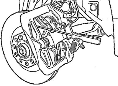
1. Remove the front wheels and secure the brake disc with the wheel bolt (see arrow in illustration).
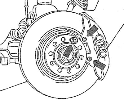
4.1 Secure the brake disc by screwing in one wheel bolt (see arrow)
2. Unscrew both caliper mounting bolts with a socket wrench (see arrows in illustration 4.1).
3. Disconnect the brake pad wear sensor plug.
4. Release the plug from the holder by prying it with a screwdriver and simultaneously turning it 90° (see illustration).
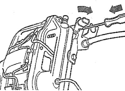
4.4. Release the plug from the holder by prying it up with a screwdriver and turning it 90° at the same time
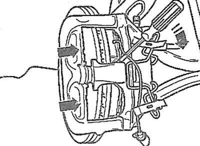
5. Use an adjustable wrench to alternately compress the upper and lower parts of the pressure spring, move them to the side and release them from the mount (see arrows in the illustration).
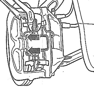
4.5. Use an adjustable wrench to release the pressure spring from the mount
6. Use a flat screwdriver to push the piston into the wheel cylinder and move the caliper outward (see arrows in the illustration).
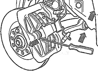
4.6. Use a flat screwdriver to push the piston into the wheel cylinder and move the caliper outward (see arrows)
Attention! If the brake fluid level in the reservoir is high, it may splash out when the piston is pressed, so in this case it is recommended to remove some fluid from the reservoir.
7. Remove the outer brake pads from the caliper by pressing them with a screwdriver to disengage the protrusions on the pads (see arrow in illustration).
4.7. Remove the outer brake pads from the caliper by pressing them with a screwdriver (see arrow)
8. Move the caliper in the direction shown by the arrows until it stops, carefully push the inner brake pads out of the cylinder cavities and remove them from the caliper (see illustration).
4.8. Move the caliper in the direction shown by the arrows
Installation
9. Clean dust and dirt from the caliper and any rust from the edges of the brake disc. If the pads are suitable for further use, clean them with a wire brush and rag.
10. Check the brake disc for cracks, wear or mechanical damage and replace it if necessary.
11. Measure the thickness of the brake disc.
12. Install the upper and lower inner brake pads with the wear sensor in the caliper and secure them in the cylinder cavity by inserting the projections on the pads inside, avoiding damage to the cylinder cuff. Secure the wear sensor wire in the holder (see arrows in the illustration).
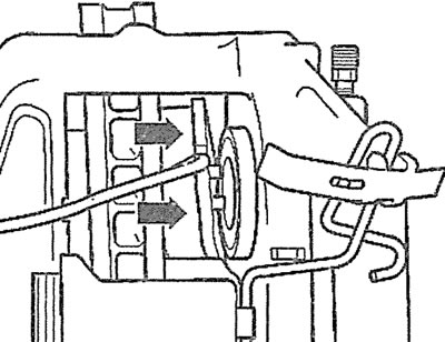
4.12. Install the inner brake pads with the wear sensor into the caliper and secure them in the cylinder cavity by inserting the protrusions on the pads inside (see arrows)
13. Move the caliper to the stop, remove the protective film from the outer brake pads, install the pads in the caliper and secure with a spring (see illustration).
14. Unscrew the wheel mounting bolt that secured the brake disc.
15. Press the brake pedal all the way down several times to allow the new brake pads to seat themselves.
[This publication is borrowed from the resource: Audimanual.ru]