
Table of contents: Description of systems ↓ Description of the refrigeration unit ↓ Safety precautions when servicing a… ↓ Refrigeration unit maintenance ↓ Autonomous fuel heater ↓
Note: The description of the climate control system is given using the example of models with a refrigeration unit.
Description of systems
The description of the climate control system is given in Chapter "Controls and operating techniques". One of the main elements of the climate control system is its block, which contains the main components: fan, radiator, evaporator and air flow distribution flaps with activators (see illustrations 7.1a-c). Before entering the air conditioning unit, outside air passes through a cabin filter designed to clean it of small particles (dust, soot, pollen, etc.); the filter should be replaced periodically (see Chapter 1). The fan is designed for ventilation of the passenger compartment, i.e. to increase the intensity of air supply to the passenger compartment of the car; the fan speed can be adjusted. To heat the passenger compartment, the coolant heated in the engine is passed through the radiator of the climate control system, giving off heat to the air passing through it. To cool the passenger compartment, a refrigeration unit is used, in which the refrigerant R134a circulating takes heat from the air supplied to the passenger compartment when the air passes through the evaporator. Along with cooling, the air is dried when passing through the evaporator, so it is recommended to turn on the refrigeration unit to reduce the humidity in the passenger compartment (for example, to speed up the removal of condensation from glass). The flaps are used to: switch between supply ventilation/air circulation modes, regulate temperature, and distribute air flows in the cabin (to the feet, to the face, on the glass and in the intermediate zones). Additional adjustment of air flows in the cabin is carried out by means of adjustable deflectors on the instrument panel. The location of the air ducts and air flow direction diagrams are shown in Illustrations 7.2a-c.
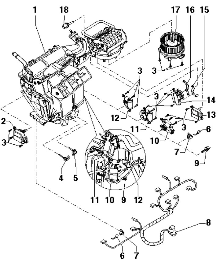
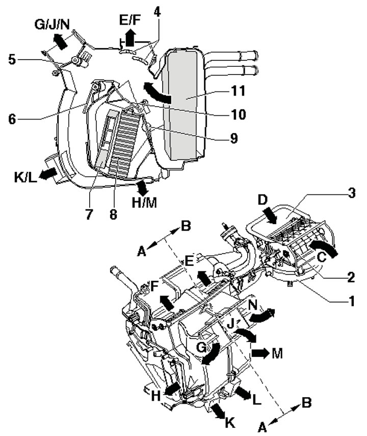
7.1a. Electrical units of the climate control system housing 1. Air conditioning unit housing; 2. Activator V158 left temperature flap (yellow lever); 3. Bolt; 4/5. Sensor G261/G262 temperature at the outlet in the left/right footwell; 6. Clamp; 7. Harness holder 8; 8. Climate control system wiring harness; 9. Evaporator outlet temperature sensor G263; 10. V159 actuator right temperature flap (purple lever); 11. V70 central flap actuator (white disc cam); 12. Activator V107 for glass blower flap (dark green lever); 13. Activator V113 fresh air flap (blue lever); 14. Activator V71 of the flow intensity control flap (blue disc cam); 15, 16. Lever; 17. Control unit J126 for supply air fan and supply air fan V2; 18. G89 air intake duct temperature sensor
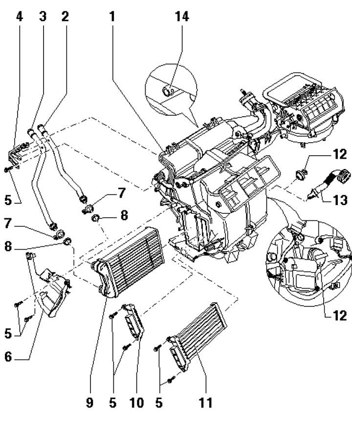
7.1b. Heating elements and air ducts of the air conditioning system housing 1. Air conditioning unit housing; 2. Coolant return pipe; 3. Coolant supply pipe; 4. Holder for pipes 2 and 3; 5. Bolts; 6. Cover of pipes 2 and 3 Clamps, subject to replacement, 2.5 Nm; 8. Sealing ring, subject to replacement; 9. Radiator; 10. Plug for the hole for installing an additional heater; 11. Additional heater radiator (some diesel models without independent heating); 12. Cork (on models without glove compartment cooling); 13. Air duct to the glove compartment; 14. Nipple for condensate drain hose
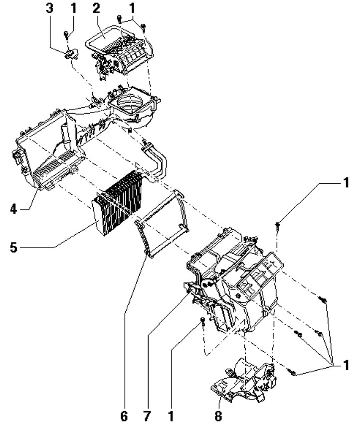
7.1c. Main nodes of the climate system housing 1. Bolt; 2. Air intake shaft with dampers for fresh air, supply air and excess air; 3. Refrigerant line holder; 4. Air duct; 5. Evaporator; 6. Evaporator seal; 7. Air distributor with temperature and distribution dampers (disassembly is not allowed); 8. Front deflector in the footwell
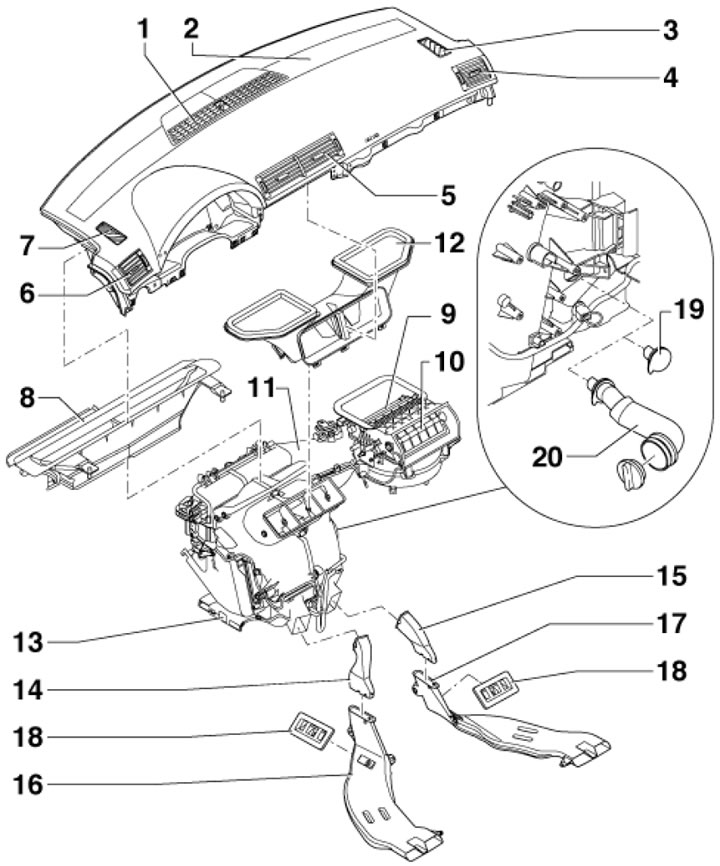
7.2a. Air ducts and deflectors 1. Windscreen deflector with solar radiation sensor G107; 2. Instrument panel; 3. Right front window deflector; 4. Right instrument panel deflector; 5. Central instrument panel deflectors; 6. Left instrument panel deflector; 7. Left front window deflector; 8. Windshield air duct; 9. Outdoor air intake; 10. Cabin air intake (circulation); 11. Climate system housing; 12. Air duct deflectors 5; 13. Deflectors in the front footwells; 14/15. Air duct connection 16/17; 16/17. Air duct to left/right rear footwells; 18. Air outlet grilles; 19. Cork (on models without glove compartment ventilation); 20. Air duct to the glove compartment
7.2b. Air distribution diagrams (the flaps are shown in the "towards the feet" position, and the temperature controller operates in the "cooling" mode, i.e. air does not pass through the radiators) A/B. Driver/Front Passenger Side; C. Cabin air intake (circulation, above the front passenger footwell); D. Outdoor air intake (through the cabin filter); E/F. To the window deflectors on the right/left; G. To the left instrument panel deflector; H. To the deflector in the front left footwell; J. To the central instrument panel deflectors; K/L. To the deflector in the rear left/right footwell; M. To the deflector in the front right footwell; N. To the right instrument panel deflector; 1. Supply fan V2 with its control unit J126; 2. Circulation flap (shown in closed position); 3. Supply dampers (shown in open position), are given independently of each other; 4. Windscreen defroster flaps (shown in closed position), are given independently of each other; 5. Central flaps "1" (shown in closed position), are given independently of each other; 6. Central flaps "2" (shown in open position), are given independently of each other; 7. Additional heater radiator (if available); 8. Radiator; 9/10. Temperature flaps "2"/"1" for left and right sides (shown in "cooling" position); 11. Evaporator
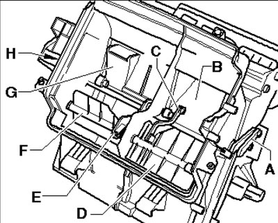
7.2c. Connecting element between temperature valves "1" and "2" A. Connecting elements related to the left temperature flap actuator; B. Temperature flap "1", driver's side; C. Connector, driver side; D. Temperature flap "2", driver's side; E. Connector, front passenger side; F. Temperature flap "2", front passenger side; G. Temperature flap "12", front passenger side; H. Connecting elements related to the right temperature flap actuator
The location of the climate control system components in the engine compartment and luggage compartment is shown in Figure 7.3.
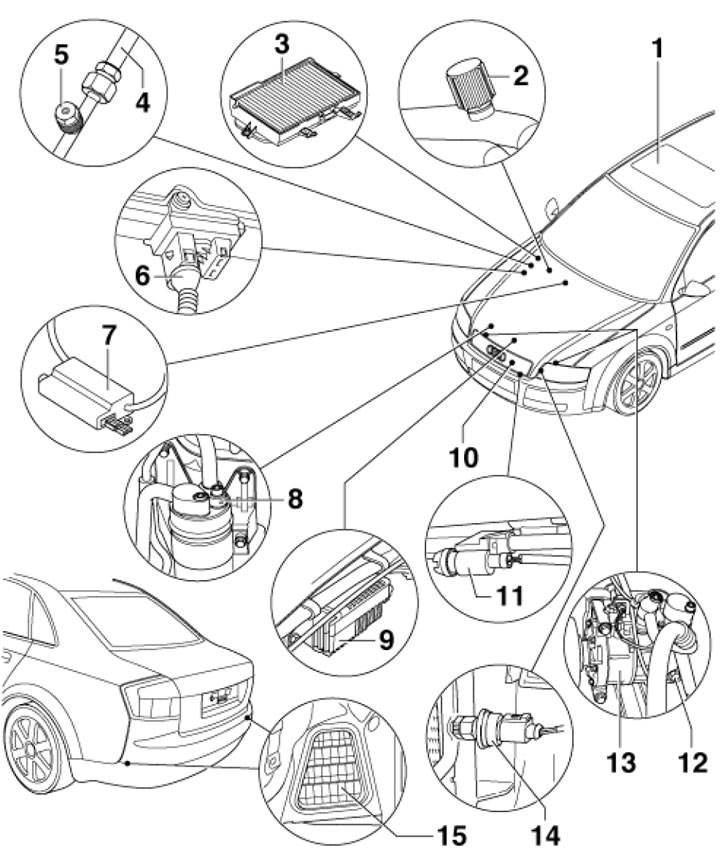
7.3. Climate control system components located in the engine compartment and luggage compartment 1. Top hatch cover with solar panels; 2. Low pressure side service connection; 3. Cabin filter; 4. Threaded connection with expansion tube; 5. High pressure side service connection; 6. Air quality sensor G238; 7. Control unit J505 for heated windscreen; 8. Accumulator-dryer; 9. Control unit J293 for cooling system fan; 10. Capacitor; 11. Sensor G17 outside air temperature; 12. Compressor regulating valve N₂80; 13. Compressor; 14. High pressure sensor G65; 15. Forced exhaust ventilation grilles
The climate control system is controlled by an electronic control unit (see chapter "Controls and operating techniques"). The dampers are driven by electronically controlled actuators (see illustrations 7.1a-c). On models with a climate control system with a cooling function, the following sensors are additionally used:
- solar radiation sensor - measures the strength of solar radiation and transmits the obtained values to the electronic control unit of the climate control system, which, when operating in automatic mode, regulates the fan speed and the position of the flaps if necessary;
- air quality sensor - determines the composition of the air at the inlet for automatic switching between supply ventilation and circulation mode;
- heater temperature sensor, cabin air temperature sensor. The electronic control unit of the climate control system uses data from these sensors as additional ones to maintain the set air temperature in the cabin. For the correct operation of the climate control system in automatic mode, do not cover the sensors.
Description of the refrigeration unit
A schematic description of the refrigerant flows is shown in Figure 7.4.
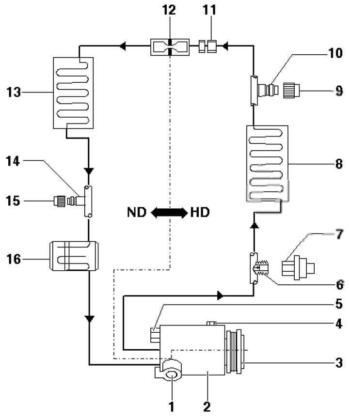
7.4. Functional diagram of the refrigeration unit. HD. high pressure side; ND. low pressure side; 1. Low pressure control valve (not removable); 2. Compressor; 3. Compressor drive pulley or assembly; 4. Oil drain plug, 30 Nm; 5. Safety drain valve (not removable),10 Nm; 6. Connection to the valve; 7. High pressure sensor; 8. Capacitor; 9. Cap; 10. Connection for service station on high pressure side; 11. Threaded connection, 15 Nm; 12. Expansion tube; 13. Evaporator, 25 Nm; 14. Connection for service station on low pressure side; 15. Cap; 16. Accumulator-dryer, 10//25 Nm (for bolts M6 // M8)
The compressor (2), driven by a belt from the engine crankshaft, sucks in gaseous refrigerant from the evaporator (13) and compresses it. In doing so, the temperature of the refrigerant rises to 70°C.
Note: On 8-cylinder engines, a drive shaft is used instead of a belt to drive the compressor.
To ensure that the compressor sucks in only gaseous refrigerant, an accumulator (16) is installed between the compressor and the evaporator, which absorbs the mixture of steam and gas coming from the evaporator. The steam turns into gaseous refrigerant. Compressor oil that gets into the circuit does not remain in the accumulator - a special hole is provided for it. Moisture that penetrates the refrigerant circuit during assembly is captured by the filter (dehumidifier), which is located in the accumulator. Thus, the compressor sucks in gaseous refrigerant with oil from the accumulator.
Under high pressure from the compressor, the refrigerant is directed to the condenser (8), where the heat from the refrigerant is taken away by the air passing through the condenser fins. Due to this heat loss, the refrigerant changes to liquid form and is directed from the condenser to the expansion tube.
The expansion tube (12) creates a narrow section in the circuit. This narrow section reduces the flow of liquid refrigerant and divides the refrigeration circuit into low-temperature zones (not less than 1 bar) and high (no more than 20 bar) pressure. In front of the expansion tube, the refrigerant under high pressure is warm (up to 60÷70°C), and behind the tube, the refrigerant under low pressure is cold (not lower than -4°C). In front of this narrow section, there is a filter for catching dirt, and behind the narrow section, there is a mesh for spraying the refrigerant before it gets into the evaporator.
In the evaporator (13), the liquid refrigerant, cooling, returns to a gaseous state, while the air passing through the evaporator is cooled and dried. The gaseous flow of refrigerant, leaving the evaporator under low pressure, again enters the compressor through the accumulator-dryer.
Compressor oil is used to lubricate the components of the refrigeration unit and circulates in the system together with the refrigerant.
Constant condensation of moisture on the evaporator after some time of operation of the refrigeration unit creates an environment favorable for the development of bacteria and other microorganisms. Together with contaminants penetrating with outside air, they can lead to the evaporator being overgrown with microorganisms and, as a result, the appearance of a musty smell. To prevent this situation, the cabin filter should be replaced regularly - this will reduce the ingress of dirt. Ultrasound or special solutions are used to clean the evaporator, for the application of which folding sprayers are used, inserted into the air conditioning unit.
To prevent evaporator icing, the refrigeration unit automatically switches off if the outside air temperature drops to +2...+7°C, as well as if the refrigerant pressure is excessively high. If the refrigerant pressure is too low (this may indicate that there is insufficient quantity or that its circuit is depressurized) the refrigeration unit also switches off automatically.
Safety precautions when servicing a refrigeration unit
Do not open the refrigerant circuit, as refrigerant may cause frostbite if it comes into contact with your skin.
Work on the refrigeration unit must be carried out in a suitably equipped specialized workshop. Maintenance of the refrigeration unit of the system should be entrusted exclusively to trained technical personnel, trained in safe working practices using the appropriate equipment and observing the rules for depressurization, as well as familiar with the methods of collecting and storing automotive refrigerant.
Avoid contact of refrigerant with skin.
Wear safety glasses when working near a refrigeration unit; when working with refrigeration oil, additionally wear oil-resistant gloves
If refrigerant gets on your skin or in your eyes, do not rub the affected area. Immediately rinse the affected area with cold water for at least 15 minutes and seek qualified medical help. Self-medication is not allowed.
The refrigerant is stored in cylinders under pressure. Store the cylinder at a temperature not exceeding +50°C. Take measures to prevent the cylinder from falling from a height or other situations that may result in its damage.
Work should be carried out in a well-ventilated area. The refrigerant evaporates quickly, reducing oxygen availability and making breathing difficult.
The gaseous refrigerant is heavier than air and should collect relatively quickly at a low level, such as under a car.
When the refrigerant burns, a toxic gas is formed. Keep the refrigerant away from open sources of fire. Do not smoke when working with the refrigeration unit.
When welding near the refrigeration unit, do not expose it to high temperatures or open flames. Overheating may cause pressure in the refrigerant circuit to increase and cause a fire.
Cleaning the condenser or evaporator with water vapor is not permitted. Only cold water or compressed air should be used.
Refrigeration unit maintenance
Caution: Servicing the refrigeration unit requires appropriate equipment and qualifications. Follow the safety precautions listed in the subsection above.
Note: The refrigerant and refrigerant are extremely hygroscopic, so close the container and the refrigeration circuit immediately after adding them. If the refrigerant circuit has been completely emptied due to depressurization (accidents or repairs), then the desiccant should be replaced because too much moisture may have entered the system.
To improve the separation of the coolant from the refrigeration oil, let the engine run for a few minutes at low speeds (800÷1200 rpm) with the refrigeration unit running. This helps to ensure that the oil is less carried along with the coolant during pumping.
Autonomous fuel heater
An additional heater is installed on diesel models and serves to preheat the engine and interior (see chapter "Controls and operating techniques").
The location of the main components of the autonomous heater, its design and connection diagram are shown in illustrations 7.5ad.
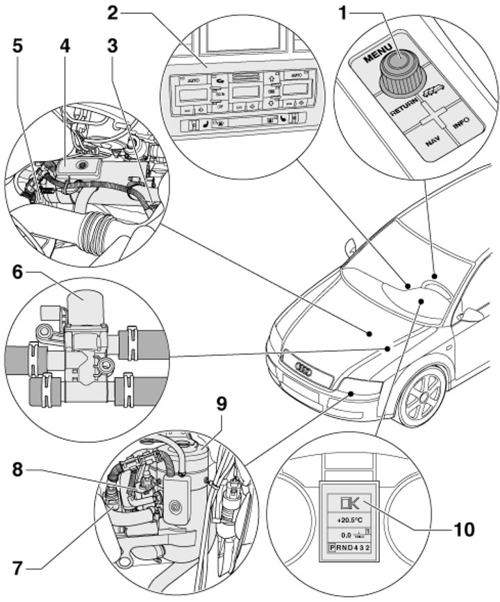
7.5a. Autonomous heater units in the front part of the vehicle 1. Switch E91 or E272 menu control; 2. Control unit J255 for air conditioning system; 3. Circulation pump V55; 4. Autonomous heater (horizontal installation); 5. Control unit J364 auxiliary heater 4; 6. Coolant shut-off valve N₂79; 7. Control unit J364 auxiliary heater 9; 8. Circulation pump V55; 9. Autonomous heater (vertical installation); 10. Display in the instrument cluster
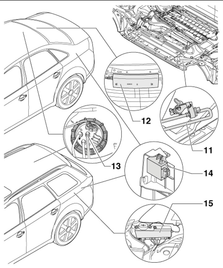
7.3b. Independent heating units in the rear of the vehicle 11. Dosing pump V54; 12. Antenna control unit; 13. Fuel supply unit; 14. Radio receiver R64 autonomous heater; 15. Left antenna module R108 Universal models
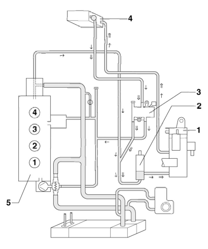
7.5s. Wiring diagram of the independent heater to the cooling system (using the example of a 4-cylinder engine with a coolant cut-off valve) 1. Autonomous heater; 2. Circulation pump V55; 3. Coolant shut-off valve N₂79; 4. Radiator in the climate control system housing; 5. Engine
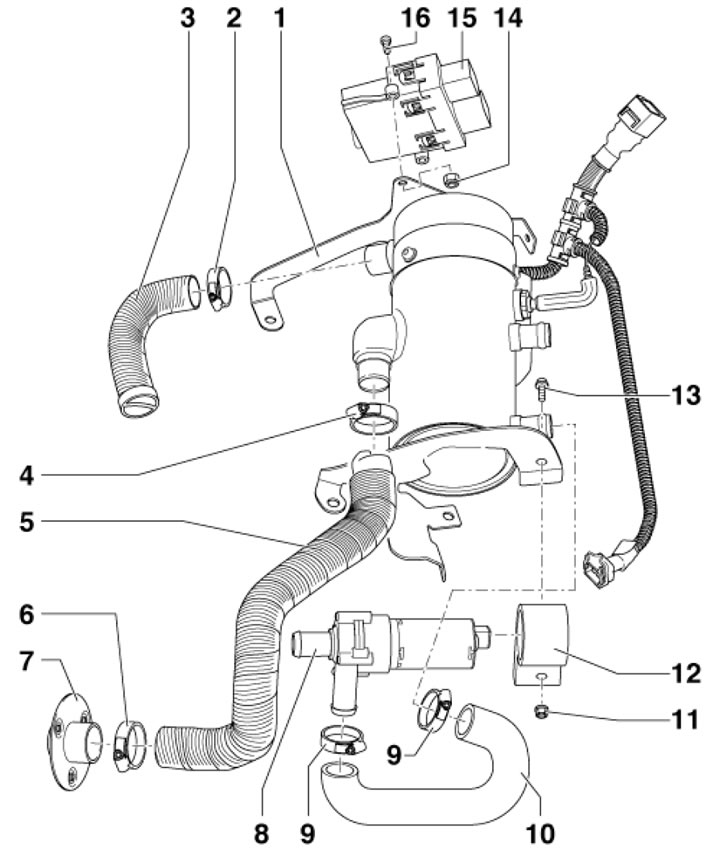
7.5d. Design of an autonomous heater (using the example of horizontal installation) 1. Autonomous heater; 2, 6, 9. Clamp; 3. Inlet hose; 4. Clamp, 7 Nm; 5. Corrugated exhaust pipe; 7. pipe tip 5; 8. Circulation pump V55; 10. Coolant hose; 11, 14. Nut; 12. Holder; 13, 16. Bolt; 15. Control unit J364 for auxiliary heater
The article is a reprint of material from AUDImanual