
Table of contents: Oil pump and oil pan. Petrol engines… ↓ Oil filter base with elements.… ↓ Oil pump and lubrication system… ↓ Chain drive oil pump. V6 engine ↓ Oil pan and oil cooler with… ↓
Oil pump and oil pan. Petrol engines 1.8 l (AVJ, BFB)
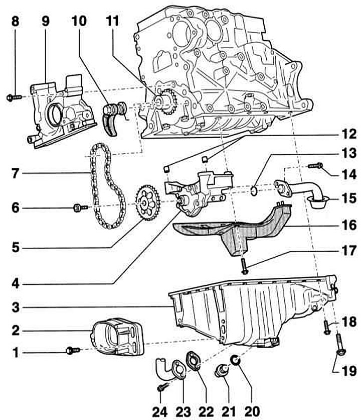
- 1 - Bolt, 28 Nm
- 2 - Torque support stop
- 3 — Oil pan
- 4 — Oil pump. With a 12 atm safety valve. Before installation, check if there are two bushings (12) for centering the oil pump on the cylinder block.
If there are grooves on the working surface and gears, replace them. Tightening torque of the oil pump cover: 10 Nm
- 5 — Oil pump sprocket. Installed uniquely
- 6 - Screw, 22 Nm
- 7 — Oil pump drive chain. Before removing, mark the direction of rotation. Check for wear
- 8 - Bolt, 15 Nm
- 9 — Front sealing flange. Installed with silicone sealant, e.g. AUDI-D 176 404 A2. Replace the sealing ring on the pulley side
- 10 — Chain tensioner, 16 Nm. Cannot be disassembled. Observe the installation position. When installing, pre-compress the spring and hook it. If the spring breaks, replace the tensioner as a set
- 11 — Oil pump sprocket
- 12 - Centering bushings, 2 pcs.
- 13 — O-ring. Be sure to replace it
- 14 - Bolt, 16 Nm
- 15 — Suction pipe. If dirty, clean the mesh
- 16 - Obstruction to flow
- 17 - Bolt, 16 Nm
- 18 - Bolts, 15 Nm. They are tightened crosswise in several steps
- 19 - Bolt, 40 Nm
- 20 — O-ring. Be sure to replace
- 21 — Oil drain plug, 30 Nm
- 22 - Seal. Be sure to replace
- 23 — Turbocharger oil return line
- 24 - Bolt, 10 Nm
Remove both rear oil pan mounting bolts (1) and (2) with a socket wrench (refer to the illustration above). To do this, on vehicles with manual transmission, turn the flywheel (3) so that the groove (arrow in the illustration below) was located opposite the screw.
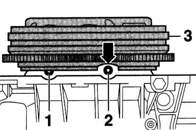
Rear oil pan mounting bolts
Preliminary tightening of bolts (1) to (18) is performed crosswise with a torque 5Nm and then in a moment 45Nm. Bolts M10 (arrows in the illustration below) tightened to a torque of 40 Nm. Bolts (1) to (18) are tightened crosswise to a torque of 15 Nm.
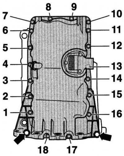
Oil pan mounting bolts
Oil filter base with elements. 4-cylinder petrol engine
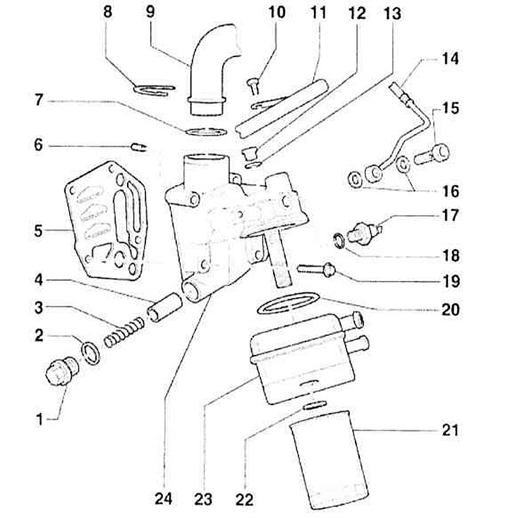
- 1 - Screw cap, 40 Nm
- 2 - O-ring. Replace
- 3 - Bypass valve spring, approximately 4 atm.
- 4 — Bypass valve piston, approximately 4 atm.
- 5 - Gasket. Replace
- 6 — Oil retaining valve, 8Nm. Mounted in the oil filter bracket
- 7 — O-ring. Replace
- 8 - Latch
- 9 — Crankcase breather pipe
- 10 - Bolt, 20Nm. When installing, use curing sealant D 000 600 A2
- 11 - Rear cooler pipe
- 12 - Screw cap, 15Nm
- 13 — O-ring. Replace
- 14 — Oil supply pipe to turbocharger
- 15 - Hollow bolt, 30Nm
- 16 — Seals. Always subject to replacement
- 17 — D/V oil pressure, 1.4 atm., 25Nm. Black insulation. If oil leaks through the sealing washer, replace the latter
- 18 — O-ring. Replace if there are oil leaks
- 19 - Bolt, 15Nm+90°. Replace
- 20 — Gasket. Replace. Insert into the protection in the oil cooler
- 21 — Oil filter
- 22 - Nut, 25Nm
- 23 — Oil cooler. Check the gap between it and the adjacent parts
- 24 — Oil filter bracket with bypass valve, approximately 4 atm.
Oil pump and lubrication system components. V6 engine

- 1 — Oil pump. Replaced as a complete assembly
- 2 — Oil spray valve, 40Nm
- 3 - O-ring. Replace
- 4 - Bolt, 45Nm
- 5 - Intermediate roller
- 6.7 - Bolt, 10Nm
- 8 — Crankcase breather
- 9 — Breather gasket/plate. Replace
- 10 — Oil control valve, 25Nm
- 11 — Connector
- 12 - Bolt, 15Nm
- 13 — Oil distribution pipe
- 14 — Cylinder block
- 15 - Bolt, 10Nm. When installing, use D6 curing sealant
- 16 — Oil sprayer. Front piston cooling
- 17 - Metal gasket. Replace
- 18 — Engine oil temperature sensor G8, 10Nm. If oil leaks through the sealing washer, replace the latter
- 19 — Seal
- 20 — Tensioner. Lock before removing
- 15 - Bolt, 10Nm. When installing, use D6 curing sealant
- 22 — Sealing ring
- 23 — Washer
- 24 — Bearing bushing
- 25 - Bolt, 25Nm
- 26 — Tensioner lever
Chain drive oil pump. V6 engine
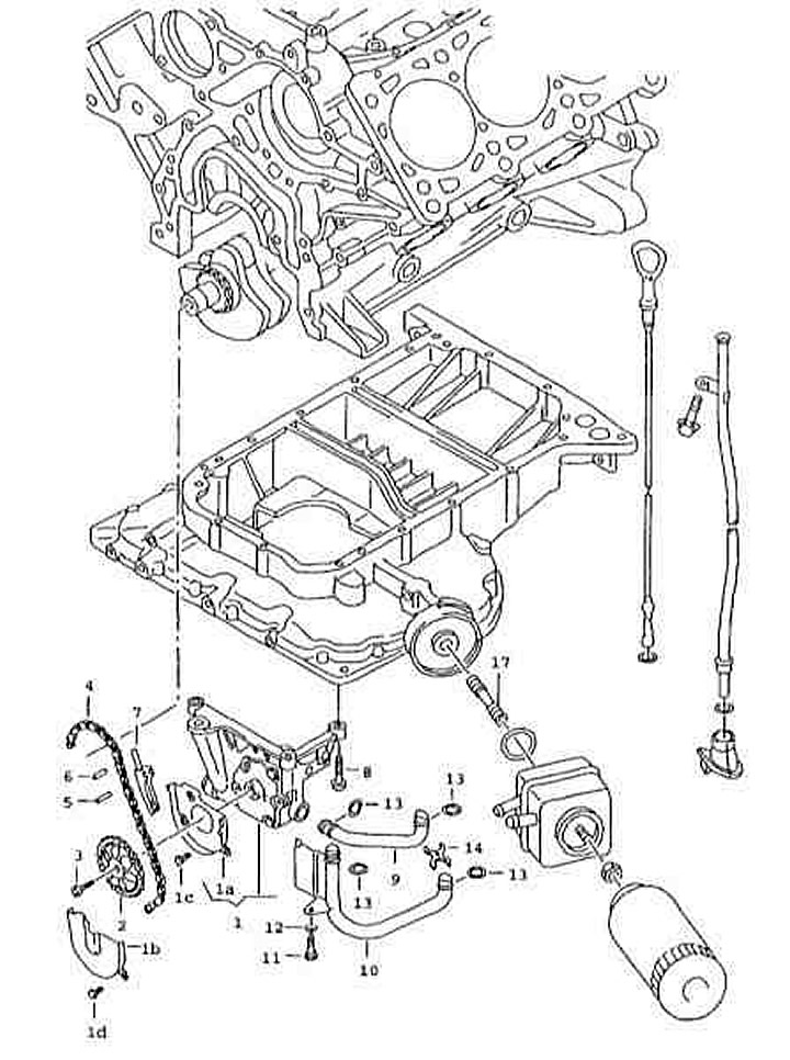
- 1 - Oil pump
- 1a, 1b - Protective plate
- 1c - Hexagon Head Self-Locking Bolt
- 1d - Hexagon head bolt
- 2 - Asterisk
- 3 - Ball-head screw
- 4 - Chain
- 5 - Control pin
- 6 - Pin
- 7 — Chain tensioner
- 8 - Hexagon head bolt
- 9, 10 — Oil pipe
- 11 - Hexagon head screw
- 12 — Washer
- 13 - Round seal
- 14 — Plate
- 17 - Connection
Oil pan and oil cooler with elements. V6 engine
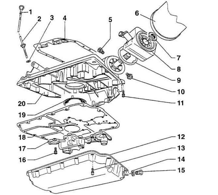
- 1 — Engine oil dipstick. The oil level should not exceed the MAX mark
- 2 — Feeler gauge guide tube
- 3 - O-ring. Replace
- 4 — Gasket. Replace. Before installation, lubricate the mating surfaces of the cylinder block with D2 grease
- 5 - Screw cap, 25Nm. If oil leaks through the sealing washer, replace the latter
- 6 - Oil filter. Loosen with a special key. Tighten by hand. Follow the instructions on the oil filter
- 7 - Nut, 30Nm
- 8 — Oil cooler. Lubricate the mating surface with AMV 188 100 02 grease
- 9 — O-ring. Replace
- 10 — D/V oil pressure (F1) 1.4 atm., 25Nm. White. If oil leaks through the sealing washer, replace the latter
- 11 - Bolt, 10Nm
- 12 — Lower oil pan
- 13 - Bolt, 10Nm
- 14 — Sealing washer. Replace
- 15 — Engine oil drain plug, 30Nm
- 16 - Bolt, 10Nm
- 17 — Oil pan cover with two bypass valves: 5 atm. and 11 atm.
- 18 — Gasket. Replace
- 19 — Oil intake. Clean if clogged
- 20 — Upper oil pan