



2. Unscrew the screws with non-falling washer 6 from the guide part 2, unscrew the screws with internal hexagon 7 and pull the trim forward together with the energy-absorbing shock absorber. After unscrewing the screws with non-falling washer from the trim, remove the crossbar. Installation is carried out in the reverse order.
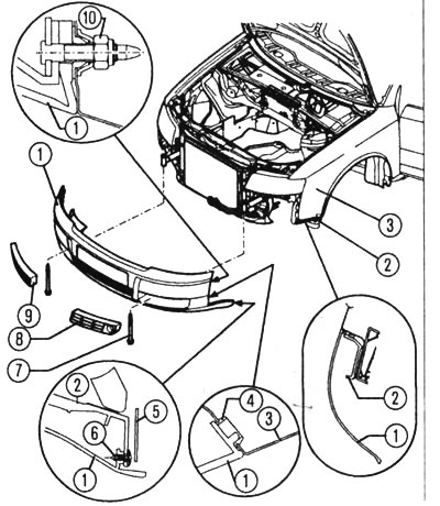
Front bumper installation diagram: 1 - shell, 2 - guide part, 3 - wing, 4 - clamp, 5 - wheel cover, 6 - screw with non-falling washer (1 Nm), 7 - screw with internal hexagon, 8 and 9 - air intake grille, 10 - hexagon nut with flange (5 Nm)
3. Before installing the front bumper, it is necessary to press the clamps into the wing. The locking lug 1 must engage with the clamp 4, and the trim 1 must engage with the guide part 2.
4. Tighten the hexagonal flange nuts 10 and the hexagonal socket head cap screws 7 (after screwing in). The energy-absorbing shock absorber is centered in height relative to the cross member independently.
5. To attach the trim 1 to the wing, place the trim with the cross member on the energy-absorbing shock absorber and fasten it on the left and right to the guide piece on the wing.
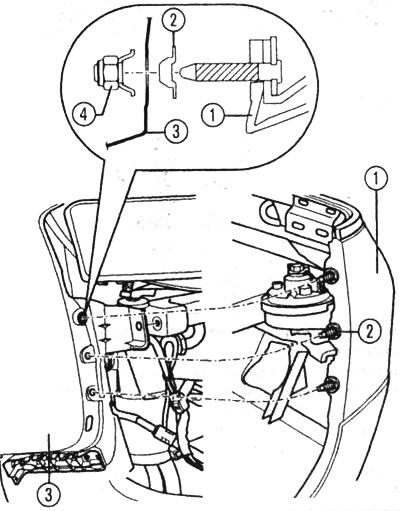
Wing trim: 1 - lining, 2 - spacer clamp, 3 - wing, 4 - hexagon nut with flange (4 Nm).
6. Using hexagonal flange nuts 4, screw the trim to the wing. Before installing the trim, it is necessary to press in the spacer clamps.