
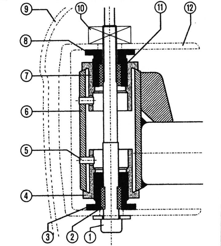
Attaching the bumper to the energy absorbing shock absorber: 1 - Allen screw (23 Nm), 2 - lower drive sleeve, 3 - lower adjustment screw (left hand thread), 4 - lower threaded sleeve (prevented from falling out by a locking pin), 5 - locking pin, 6 - energy absorbing shock absorber, 7 - upper threaded sleeve (prevented from falling out by a locking pin), 8 - upper adjustment screw (right hand thread), 9 - lining, 10 - nut, 11 - upper drive sleeve, 12 - crossbar.
2. Before installing the front bumper, fully tighten the upper (B) and lower (3) adjusting screw.
3. If you need to dismantle the guide part, you need to remove the bumper. To dismantle, unscrew screws 2.
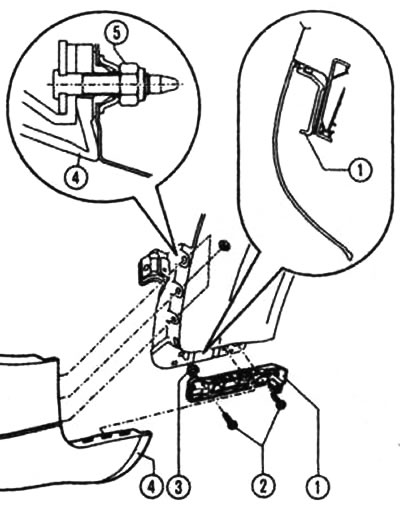
Guide piece: 1 - guide part, 2 - screw (1.5 Nm), 3 - clamp, 4 - lining, 5 - hexagon nut with flange (4 Nm).
4. When installing, the lining must carefully engage with the guide part 1. Access to the hexagonal nut with a flange 5 can only be obtained after loosening the front half of the wheel housing.