
To bring the lock bracket to the service position, it is only necessary to loosen the screws of the quick-release connections 1. If the rear sound insulation is attached at the same time, longer screws must be used for position 4. Please note that the designation (notch) on the support 7 for the sound insulation must be directed towards the left side of the car.
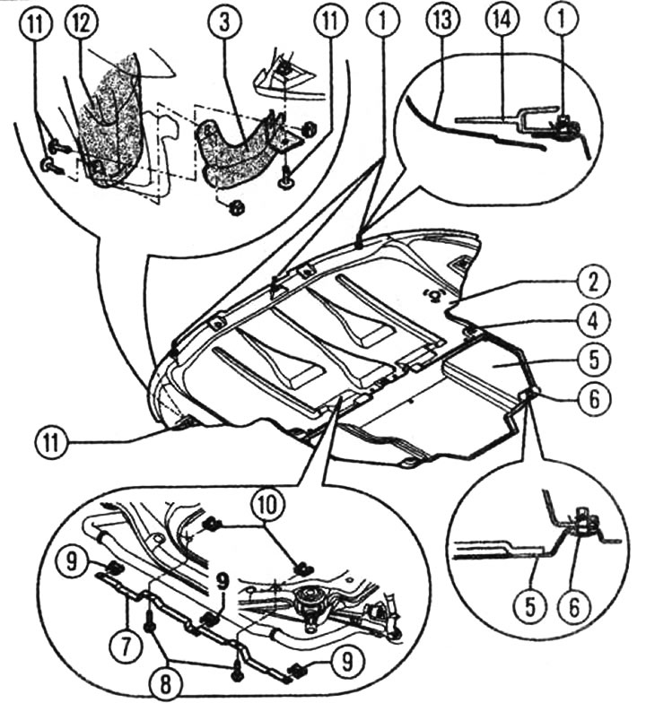
Soundproofing installation diagram: 1 - three quick-release screws, 2 - front sound insulation, 3 - wheel spoiler, 4 - three quick-release screws, 5 - rear sound insulation (only in some engine variants), 6 - two quick-release screws, 7 - soundproofing support, 2 - two screws (7 Nm), 9 - three self-locking sheet metal nuts, 10 - two self-locking sheet metal nuts, 11 - six clamping pins, 12 - wheel cover, 13 - bumper, 14 - lock bracket with parts
[The article is a reprint of material from audimanual.ru]