
Table of contents: Pressure regulator ↓ Checking injection valves ↓ Checking the coolant temperature… ↓ Checking the intake air temperature… ↓ Fresh air flow meter ↓ Removal injection valves ↓
Pressure regulator
To measure pressure, a suitable pressure gauge is required (V.A.G 1318) with shut-off valve and adapter.
Nominal value at idle speed is about 3.5 bar; in the vacuum hose removed from the pressure regulator, about 4 bar.
The minimum pressure maintained immediately after switching off the engine is at least 3 bar; after 10 minutes about 2.5 bar.
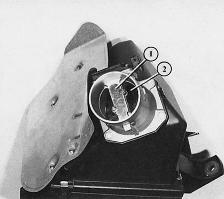
Checking injection valves
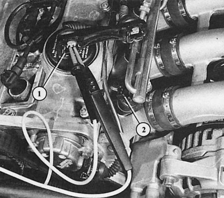
Here the connector (1) of the injection valve (2) is disconnected. The voltage indicator with LED checks the voltage supply to the injection valves.
1. Checking the voltage supply: remove the 1.6L engine compartment trim (Chapter Body parts); for a 1.8L engine, first pull up on the rear edge of the cover above the injection valves, then remove it from the front.
2. Disconnect the injection valve connectors. To do this, press the wire clips on the back side.
3. Connect a voltage indicator with an LED to the contacts of the disconnected connector.
4. Have your assistant turn the engine over with the starter.
5. The voltage indicator LED should flash, otherwise the defect is in the wire connected to the injection valves or in the Motronic control unit itself.
6. Checking the injection valves: Disconnect all injection valve connectors.
7. Connect an ohmmeter to both contacts of the first injection valve.
8. Nominal value: 14-16 W (1.6L engine) and 11–13 W (1.8L engine).
9. Deeper inspection (type of jet and tightness):
10. Remove the injection valves together with the distribution pipe – see the chapter above. But the wire connectors remain connected and the fuel lines screwed on.
11. Close the holes in the injection valves with suitable plugs.
12. Place the injection valves into four measuring cups.
13. Have your assistant turn the engine over with the starter for a few seconds: the injection stream should be the same for all valves. Then the jet pattern is OK.
14. Disconnect all injection valve connectors.
15. Turn off the ignition and then turn it on for about 5 seconds: no more than 2 drops should come out of each valve. In this case, the valves are sealed.
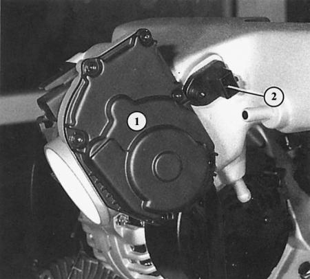
For a turbo engine, the intake air temperature sensor (2) is located on the intake manifold behind the throttle control unit (1).
This 1.8L engine with air conditioning has two temperature sensors on the flange behind the cylinder head. The number "1" is the air conditioning sensor. The number "2" is the ignition/injection system and temperature indicator sensor.
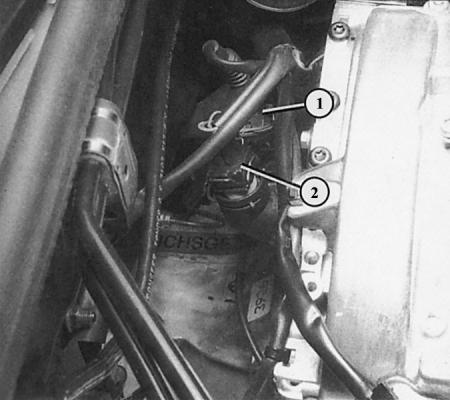
For a 1.6L engine, the temperature sensor is located in the same place.
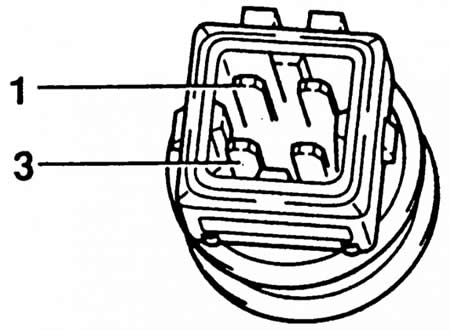
The figure shows the placement of the sensor pins.
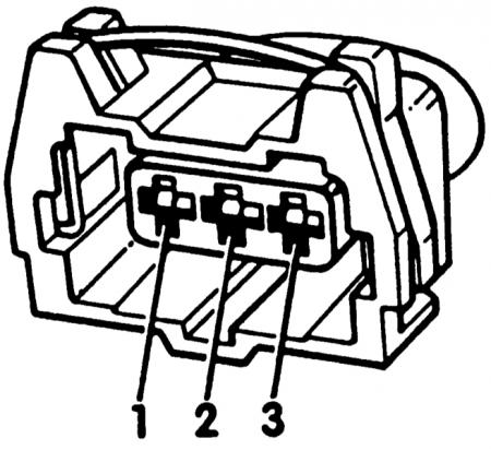
The figure shows a fresh air flow meter flanged to the air filter of naturally aspirated engines with a displacement of 1.6 and 1.8 liters.
- 1 - support of the hot-wire conductive plate;
- 2 - air passage.
The three-pole connector pinout information is used to test the fresh air flow meter in naturally aspirated 1.6L and 1.8L engines.
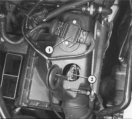
In the 1.8-litre turbo engine, the fresh air flow meter is integrated into the air filter housing. The connector (2) is accessible from above.
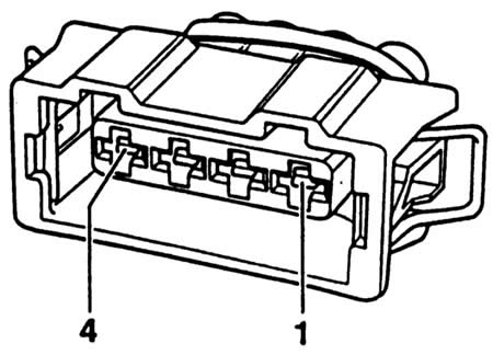
The information on the four-pole connector pin assignment is used when testing the fresh air flow meter of a 1.8L turbo engine.
Checking the coolant temperature sensor
The coolant temperature sensor is a dual-function device, which provides information to the ignition/injection system with one pair of contacts and to the combined instrument with the other pair of contacts. Here we are checking the unit associated with the ignition/injection system.
1. Disconnect the sensor connector in the coolant supply pipe behind the cylinder head.
2. Connect the ohmmeter to contacts "1" and "3" of the sensor connector.
3. Read the resistance value when the engine is cool and at room temperature (about 20°C).
4. Nominal value: 1.5–3.0 kOhm.
5. If the nominal value is obtained, the sensor is normal.
Checking the intake air temperature sensor
1. Disconnect the connector on the sensor.
2. Connect the ohmmeter to the sensor connector contacts.
3. Read the resistance value when the engine is cool and at room temperature.
4. Nominal value: 1.6–2.8 kOhm.
5. If the nominal value is obtained, the sensor is normal.
Fresh air flow meter
You can check the voltage supply to the fresh air flow meter and the signal flow through the wires to the control unit yourself. If both are OK, then if there is a defect in this unit (conduct a computer survey) the fresh air flow meter is considered faulty:
1. Disconnect the connector on the fresh air flow meter.
2. Look at the numbering of the contact tabs in the figure.
3. Voltage test: For 74 kW and 92 kW motors, connect a diode test lamp between terminal "3" on the three-pole connector of the connected wire and "ground" (engine block).
4. For a 110 kW turbo engine, connect the diode test lamp between terminal "3" on the four-pole connector of the connected wire and ground (engine block).
5. Have your assistant turn the engine over with the starter (the engine may even start): the LED should flash, in which case voltage is supplied.
6. Checking the signal flow: Turn off the ignition. Disconnect connector "A" on the control unit.
7. Using an ohmmeter, check the conductivity of the wires:
8. With 74 kW and 92 kW engines from pin "1" on the control unit connector "A" to contact "2" on the three-pin connector of the fresh air flow meter. In addition, from pin "9" on the control unit connector "A" to contact "3" on the three-pin connector of the fresh air flow meter.
9. With a 110 kW turbo engine, from pin "1" on the control unit connector "A" to contact "4" on the four-pin connector of the fresh air flow meter. Also from pin "9" on the control unit connector "A" to contact "2" on the four-pin connector of the fresh air flow meter.
Removal injection valves
1. Remove the engine compartment trim of the 1.6L engine (Chapter Body parts); with a 1.8L engine, first pull the trim up by the rear edge, then remove it from the front side.
2. Disconnect the vacuum hose from the fuel pressure regulator.
3. To relieve pressure, open the fuel tank cap briefly.
4. Loosen the screw connection of the fuel supply line. Be careful! Residual pressure! When opening the line, cover it with a rag. Let the leaking fuel drip into the rag.
5. Remove the fuel recirculation line.
6. Disconnect the injection valve connectors. To do this, press the wire clips on the back side.
7. For engines with a displacement of 1.8 L, disconnect the Hall sensor connector.
8. Unscrew both fuel distribution pipe mounting bolts.
9. Remove the fuel distribution pipe together with the injection valves.
10. If you need to remove one injection valve, remove the mounting clamp and take the valve out of the distribution pipe.
11. During installation, ensure that the sealing rings and O-rings are replaced.
12. When replacing the round rubber ring, do not under any circumstances press the plastic cap on the valve.
13. Before installation, lubricate all rubber parts with oil. Insert the valves together with the distribution tube.
Plug connectors at the rear left in the engine compartment in the 1.6L engine
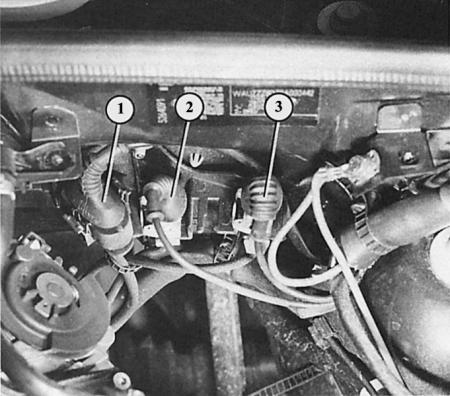
- 1 - Lambda probe plug connector (black);
- 2 - knock sensor plug connector (green);
- 3 - plug connector of the engine speed sensor (gray).
Plug connectors at the rear left in the engine compartment in the 1.8L engine
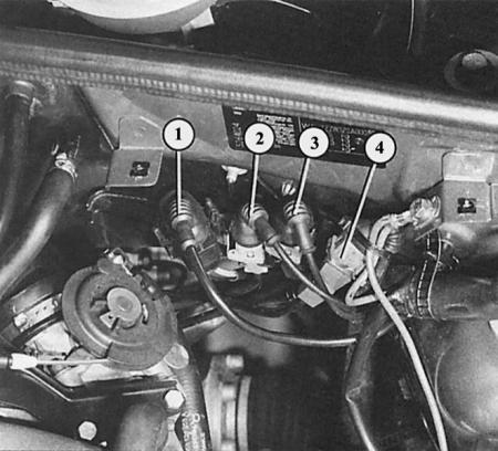
- 1 - Lambda probe plug connector (black);
- 2 - Engine speed sensor plug connector (gray);
- 3 - plug connector of knock sensor I (green);
- 4 - plug connector of knock sensor II (blue).