
Table of contents: Examination ↓ Removal ↓
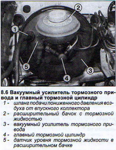
Disc brakes, unlike drum brakes, do not have a braking effect booster. Therefore, to ensure proper braking action, it is necessary to apply more force to the brake pedal. About 60% of this force is provided by the brake drive vacuum booster, connected to the main brake cylinder. At the same time, the brake pedal is also directly connected to the piston of the main brake cylinder. This design solution is forced in case of failure of the vacuum booster.
The vacuum booster is supplied with reduced pressure from the intake manifold via a corresponding hose. When braking, the difference between atmospheric pressure and air pressure from the intake manifold causes a large elastic membrane to shift, which additionally acts on the piston of the main brake cylinder. When the engine is turned off, the vacuum booster does not provide additional assistance when the brake pedal is pressed. If the engine suddenly stalls, the created reserve of reduced pressure is enough for several more brakings.
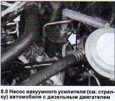
Diesel-powered vehicles are equipped with a pump that supplies reduced pressure to the vacuum booster, since there is none in the intake manifold (see illustration 8.0).
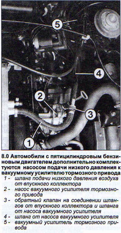
To improve the operation of the vacuum booster, cars with a five-cylinder petrol engine are additionally equipped with a corresponding pump. This pump is driven by the camshaft and is located on the left side of the cylinder head (see illustration 8.0a).
Examination
1. Turn off the engine.
2. Press the brake pedal 10 times.
3. Leave the brake pedal depressed and start the engine. If the brake booster is normal, the brake pedal will move down a little more when the engine is running. If this does not happen, the booster is faulty. The most likely cause of the defect is a leak in the low-pressure air supply hose from the intake manifold, a faulty check valve on the low-pressure hose, wear of the rubber sealing ring between the master cylinder and the booster, or the booster cuff.
4. Disconnect the low-pressure air supply hose from the vacuum booster to check the check valve. When blowing, the valve should freely pass air, blocking its access when sucking. The check valve is supplied with the hose.
5. Remove the master brake cylinder if the cause of the brake booster failure is the sealing ring between the cylinder and the booster.
6. Replace the brake booster if it is faulty. The brake booster cannot be repaired (see illustration).
Removal
7. Remove the brake master cylinder.
8. Disconnect the low pressure air supply hose.
9. Remove the trim under the instrument panel in the driver's side footwell.
10. Remove the pivot shaft from the vacuum booster drive rod fork, working in the footwell.
11. Unscrew the self-locking nuts securing the vacuum booster to the dividing wall from the passenger compartment side.
12. Unscrew the two nuts above the vacuum booster in the engine compartment.
13. Remove the vacuum booster.
When installing a new vacuum booster, it is necessary to adjust the length of its drive rod. The adjustment is performed before installing the new booster. The distance between the middle of the fork and the installation surface on the four stop pins should be 271 mm (tolerance - 0.5 mm).
14. Tighten the lock nut after completing the tie rod adjustment.
15. Lubricate the fork shaft with a thin layer of grease. Replace the old self-locking nuts and shaft mounting brackets with new ones.
16. Don't forget to install a new sealing ring between the master cylinder and the brake booster.
(The original article is available on the online resource: Audimanual.ru)