
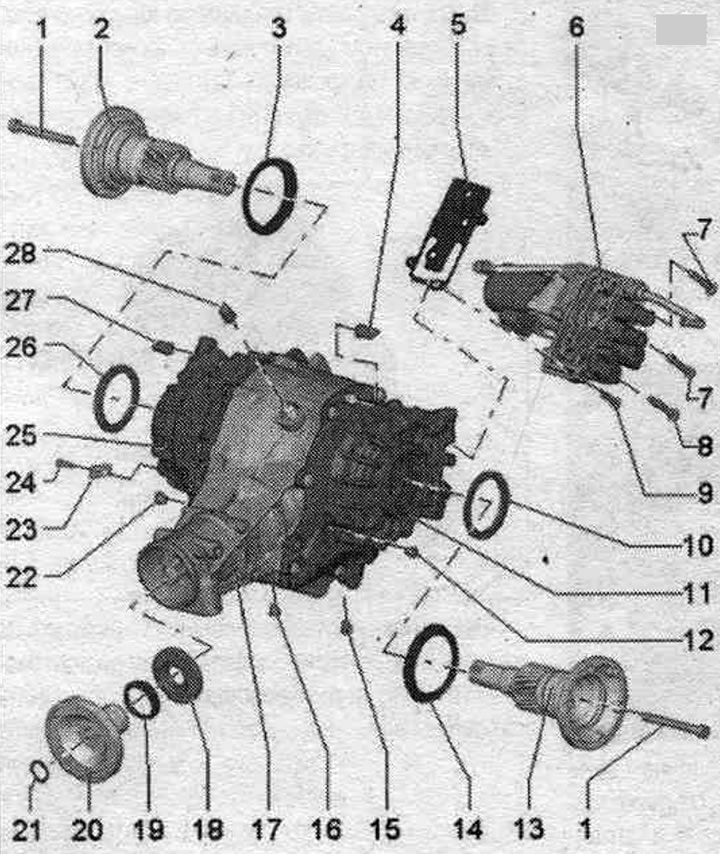
1. Bolt: 50 Nm + 180° turn, always subject to replacement.
2. Right flanged axle shaft: not to be confused with left flanged axle shaft; they are different.
3. Protective ring.
4. ATF breather: for left side attachment; fix on the air bleed tube.
5. Gasket: with mesh.
6. Hydraulic control unit: with pump for floor. "V415" drive and pipelines to the overhead units.
7. Bolt: 20 Nm, 2 pcs.; M8; length 50 mm; observe the sequence. puffs.
8. Bolt: 20 Nm; M8; length 50 mm; with non-removable seal. ring under the bolt head; lubricate the threads with sealing paste -D 176 501 A1-; observe the sequence, tightening.
9. Bolt: 20 Nm; M8; length 30 mm; observe the sequence, tightening.
10. Shaft seal: for left shaft with flange, replace.
11. Left patch unit.
12. ATF inspection plug: 15 Nm; always subject to replacement; with non-removable seal. ring.
13. Left flanged axle shaft: not to be confused with the right flanged axle shaft; they are different.
14. Protective ring: replace.
15. ATF drain plug: 15 Nm; always subject to replacement; with non-removable seal. ring.
16. Oil drain plug; 15 Nm; always subject to replacement; with non-removable seal. ring.
17. Carter main transmission.
18. Shaft seal: for flange/cardan shaft.
19. Protective ring: replace.
20. Flange/propeller shaft.
21. Retaining ring: always replaceable.
22. Oil check plug: 15 Nm; always subject to replacement; with non-removable seal. ring.
23. Holder: for wire harness.
24. Bolt: 9 Nm.
25. Right patch knot.
26. Shaft seal: for right shaft with flange; replace.
27. ATF breather: for right side attachment; fix on the air bleed tube.
28. Breather for head. transmissions; fix on the air bleed tube.
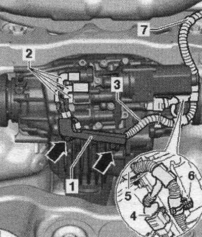
Removal and installation of hydraulics, control unit
The ignition is off. Place the car on a lift. Lower the back of the system slightly. exhaust system and secure it, if necessary, remove the rear part of the system. release. If present, unscrew the "arrow" bolts and remove bracket "1" for the wiring harness from the rear. main transmission. Mark connectors "2" for the pressure and temperature sensors, oil, and clutch valves. Remove connectors "2" from the pressure and temperature sensors, oil and clutch valves. Remove connector "4" from the floor pump. drive "V415". Then unfasten the wiring harness "3" from the main transmission and subframe -pos. 5...7- and tie it from above. Place a tray under the rear head. transmission. Drain the ATF from the rear main transmission. Drain the oil from the rear. main transmission. Remove the pump for the floor. "V415" drive. To loosen and tighten the nut for the right pipeline to the hydraulic block, the pump for the floor must be removed. drive "V415".
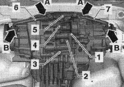
Loosen the left pipeline "6" and the right pipeline "7" to the hydraulic control unit "1" by 1 turn "arrow A" and unscrew them from the union nuts "arrows B". Unscrew the bolts "2...5" and remove the hydraulic control unit "1" with the gasket.
Installation
The old sensors should be reinstalled if possible.
Conditions: Replace the seal between the hydraulic. control unit "1" and crankcase ch. transmission. The centering pins must be installed in the hydraulic housing. control unit. To install the hydraulics, control unit "1" to the rear main transmission, the left "6" and right "7" pipes must be freely screwed into the control unit. Install the hydraulic control unit "1" to the rear main gear as follows. First, hand-tighten pipes "6" and "7" into the "arrow B" attachments. Then hand-tighten bolts "2...5," making sure bolt "2" has a permanent seal. the ring under the head and the thread of this bolt are lubricated with sealing paste -D 176 501 A1-. After this, tighten bolts "2...5" in sequence. "4", "2", "5" and "3" (M8 x 30 mm) the required tightening torque. Then tighten the nuts "arrows A" and "arrows B" of the left "6" and right "7" pipelines to the specified tightening torque. Install a floor pump. "V415" drive. Secure wiring harness "3" to the final drive and subframe - pos. 5...7-. Attach connectors "4" and "2", paying attention to the markings applied before removal to ensure they correspond to the pressure and temperature sensors, oil sensors, and clutch valves. If present, install bracket "1" for the wiring harness to the rear head. transmission, tighten the arrow bolts to the specified tightening torque. In this case, the wiring harness "3" should not be pinched. Correspondence of connectors for pressure and temperature sensors, oil and clutch valves.
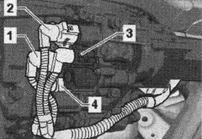
"1" = connector for oil pressure and temperature sensor 2 "G640"
"2" = connector for oil pressure and temperature sensor "G437"
"3" = Connector for clutch valve 2 for PTO "N446"
"4" = connector for clutch valve for pol. drive "N445"
Add oil to the rear chap. transmission and check its level. Filling ATF oil into the rear chap. transmission and check the ATF level. Install the rear exhaust system. and align without fur. stresses.