
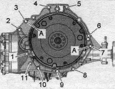
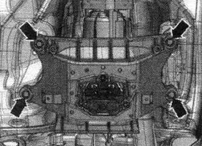
Make sure that the guide bushings "A" for aligning the engine and gearbox in the cylinder block are present; if necessary, insert the missing bushings. If necessary, check for reuse and mark the aluminum bolts "2...11" connecting the engine and gearbox.
Install the clutch module if necessary.
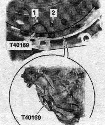
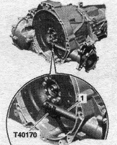
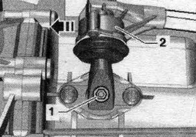
Before connecting the engine and gearbox, carry out the following preparatory actions. Insert mont. device "T40169" from below into the gearbox housing and install the clutch module as shown in the figure. Mounting tool "T40169" should fit into semicircular groove "1" and additionally into inspection hole "2." To locate the inspection hole, it is necessary to rotate the clutch module. Insert mounting bolts. devices into the hole on the gearbox housing.
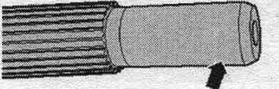
Install the "T40170" transport protection from below under the gearbox housing and attach it to the shaft with flange "1".
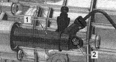
Raise the gearbox so that clutch slave cylinder "1" can be installed. Tighten bolt "2".
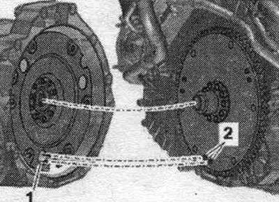
The next step is only necessary if the driven disc with locking pin "2" is installed. Additionally, align the position of the driven disc in relation to the clutch module so that locking pins "2" (if available) on the driven disk could enter the large holes "1" on the clutch module. If the retaining pins of the driven disk "2" do not enter the holes of the clutch module "1", this can lead to serious problems in the operation of the clutch.
Install the gearbox on the engine and tighten bolts "3...11". Install the starter and tighten bolts "1" and "4".
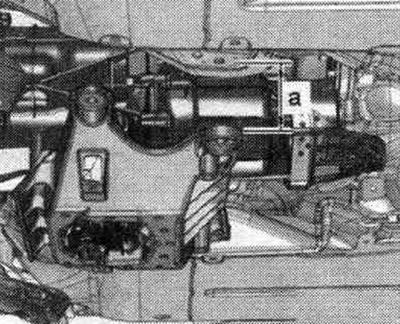
Raise the gearbox using a powertrain lift until the gap "a" between the tunnel crossmember and the body is reached. Gap size "a" = not less than 100 mm.
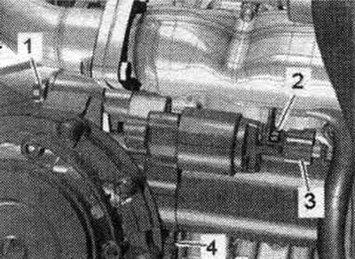
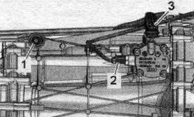
Tighten shift fork rod "1". Tighten connecting rod "3". Attach connector "2" of gear detection sensor "F208".
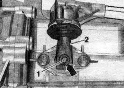
Install gearshift lever "2" as follows: gearshift lever "2" can be installed on shift shaft "1" in only one position (the notch in the gear ring "arrow"). Tighten gearshift lever "2".
Disconnect the "10-222 A/11" spindle. Continue lifting the gearbox and tighten the tunnel crossmember "arrow" bolts. Remove the tilter and mounting. bracket "T40173".
Bolt the left and right drive shafts to the shafts with the gearbox flange.
Install the drive shaft heat shield.
Install the cardan shaft. Secure the cardan shaft. To do this, install the support "T10172" with "T10172/5" on the bolts securing the propeller shaft to the gearbox or rear final drive.
Bolt tightening sequence - clutch module to driven disc
Remove mounting tool "T40169" and transport protection "T40170". Engage 6th gear by removing shift shaft "1" and shifting gearshift lever "2" forward in the direction of the arrow.
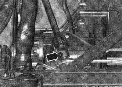
The next stage of work is absolutely necessary to ensure uniform contact with the driven disk without distortion. Rotate both fronts. wheels in one direction so that the clutch module makes 1 full revolution. The inspection hole "arrow" should be visible again in the recess of the gearbox housing.
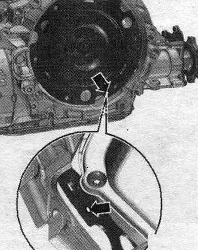
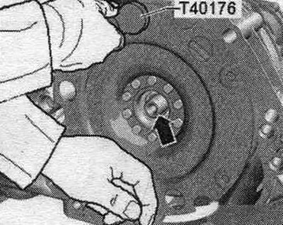
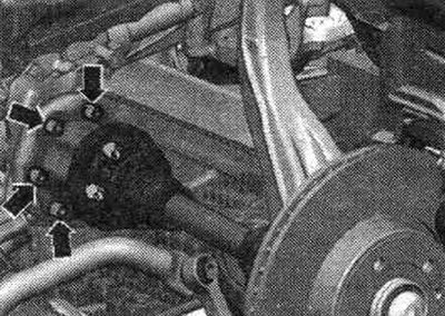
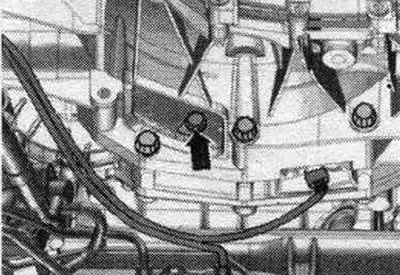
Tighten the clutch module bolts to the driven disc as follows. Use new bolts. Tighten the bolts with a 16 mm ring spanner "VAG1332/14". Tighten the first bolt "arrow" by hand (2 Nm). Turn the clutch module by both front. wheels 180° in the direction of engine rotation.
Screw in and tighten the 2nd bolt. Now screw in the remaining bolts one by one and tighten them immediately (even a bolt that has just been screwed in). Installation in reverse order. Bolt the universal joint to the steering gear.
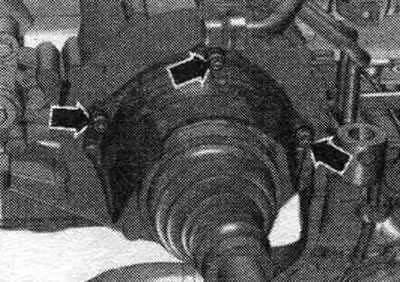
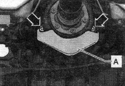
If present, install the heat shield for the driveshaft "A" and tighten the "arrow" bolts to 25 Nm.
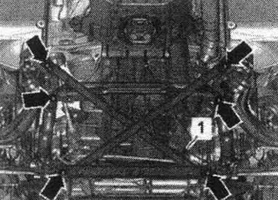
Install the right catalytic converter. Install add. mufflers left and right. Align the system. exhaust gas release without mechanical stress. Install the subframe crosspiece. Check the manual transmission oil level. Install noise-insulating shields. Install the front wall of the water drainage box. Pay attention to the battery installation work.
Tightening torques (Nm)
| Bolts and nuts | M6 | 9 |
| M7 | 15 | |
| M8 | 20 | |
| M10 | 40 | |
| M12 | 65 |
PTO shaft heat shield - tightening torque
Tighten the drive shaft heat shield arrow bolts to 23 Nm.
Fastening the engine to the manual transmission
| Pos. | Bolt | Nm |
| 1 (1) | M10 x 50 (2) | 65 |
| 2 (1), 3...6 | M12 x 100 (3) | 30 + 90° |
| 7 | M12 x 125 (3) | 30 + 90° |
| 8, 11 | M10 x 60 (3) | 15 + 90° |
| 9, 10 | M10 x 95 (3) | 15 + 90° |
| A | Centering bushings | |
(1) Additionally secures the starter.
(2) Bolt strength 10.9; this steel bolt can be used repeatedly.
(3) Check the reusability of aluminum bolts and replace if necessary.
The article is a reprint of material from: AudiManual.ru