Repair Chevrolet Repair Toyota Repair Honda Repair AvtoVAZ Repair Mercedes-Benz Repair BMW Repair Opel
Home  |  Contacts  |  Sitemap  |    
English Русский
Български
Беларускі
Український
Српски
Hrvatski
Română
Polski
Slovenský
Magyar
AudiManual.ru


  • AUDI 80
  • AUDI 100
  • AUDI A3
  • AUDI A4
  • AUDI A6
  • AUDI A8
  • AUDI Q
  • OTHER
  • ARTICLES
B8 (2007-2015) B7 (2004-2008) B6 (2000-2006) B6 (2000-2006, petrol) B5 (1994-2001) B5 (1994-2001, petrol)

Removal the gearbox — vehicles with a 3.2 l FSI engine (Audi A4 B8)

  • Home
  • Audi A4
  • B8 (2007-2015)
  • Transmission
  • Manual gearbox 0B2
  • Removal the gearbox — vehicles with a 3.2 l FSI engine
            0
Switch off the ignition. Disconnect the battery. Remove the rear engine cover "arrows". Remove the front wheels: right and left.

Switch off the ignition. Disconnect the battery. Remove the rear engine cover «arrows». Remove the…


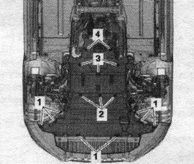
Remove the sound insulation on the right and left "1" in the wheel arch.

Remove the sound insulation on the right and left «1» in the wheel arch.


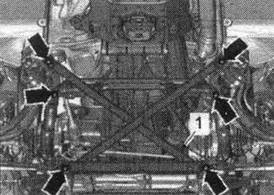
Remove the noise insulation screens by loosening the fastening elements "1, 2, 3, 4". Remove the front mufflers on the left and right. Remove the front wall of the water drainage box.

Remove the noise insulation screens by loosening the fastening elements «1, 2, 3, 4». Remove the…


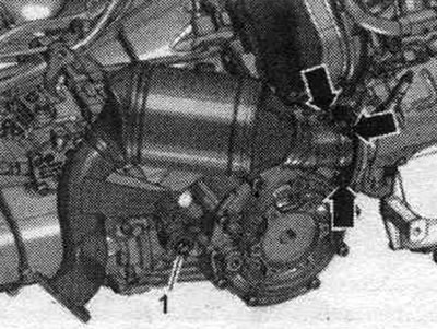
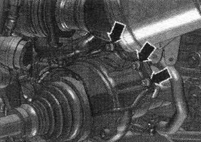
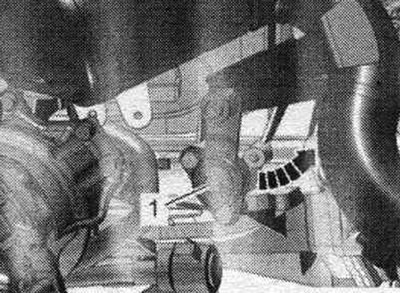
Unscrew the nuts "arrows" and bolts "1" and push the right catalytic converter to the side. For better understanding of the montage. the position is shown with the engine removed.


Unscrew the nuts «arrows» and bolts «1» and push the right catalytic converter to the side. For…


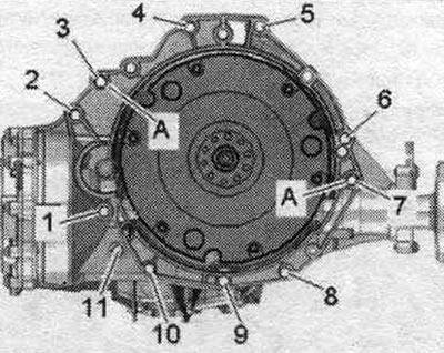
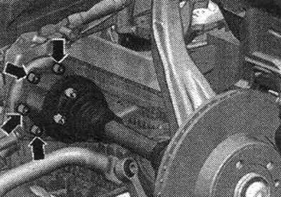
Unscrew the bolts "2...6" securing the engine to the gearbox, which are accessible from above. Secure the right catalytic converter to prevent it from falling by loosely tightening the nut.

Unscrew the bolts «2...6» securing the engine to the gearbox, which are accessible from above.…


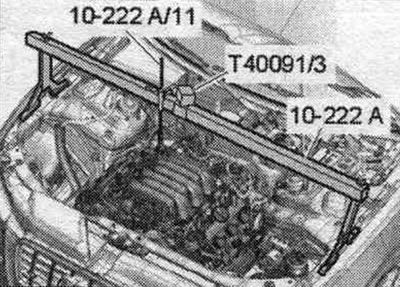
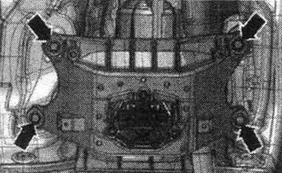
Install the "10-222 A" crossmember with the "T40091/3" connector on the shock absorber strut cups on the left and right, as shown in the figure. Secure the lead screw "10-222 A/11" to the right engine mount eye.

Install the «10-222 A» crossmember with the «T40091/3» connector on the shock absorber strut cups…


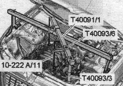
Install other parts of the "10-222 A" crossbar as shown in the figure. To do this, install the "T40093/3" support on the fold of the side member sheet. Attach the lead screw "10-222 A/11" to the left front engine mount eye.


Install other parts of the «10-222 A» crossbar as shown in the figure. To do this, install the…


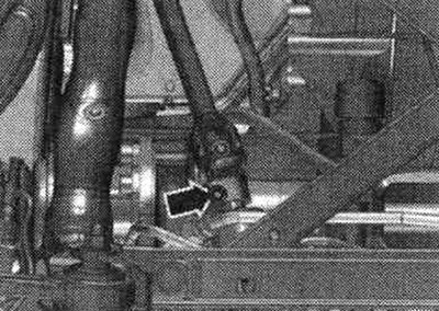
Disconnect the cardan joint from the steering gear only when the front wheels are installed straight. wheels. Do not change the position of the steering wheel or steering gear; if necessary, secure the steering wheel with duct tape. Unscrew the "arrow" bolt of the universal joint. Press the steering gear cardan joint and move it fully upward.

Disconnect the cardan joint from the steering gear only when the front wheels are installed…


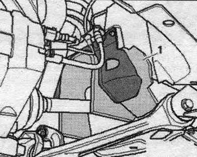
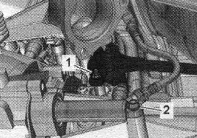
Remove bolt "1" from the power steering hydraulic line. Never lower the vehicle onto its wheels unless the subframe support, steering gear, or subframe cross-joint are properly installed. Supporting the car on a subframe or subframe struts (for example, on a mobile jack) not allowed! Loosen the "arrow" bolts and remove the subframe crosspiece.

Remove bolt «1» from the power steering hydraulic line. Never lower the vehicle onto its wheels…


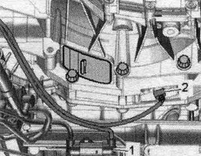
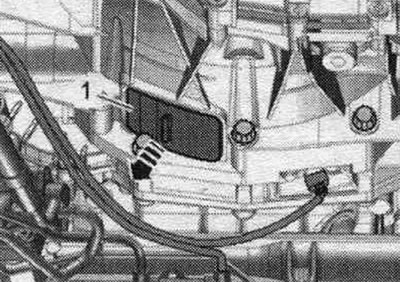
Disconnect connector "2" of engine speed sensor "G28" and release the wire from the fasteners. "Pos. 1" should not be taken into account.


Disconnect connector «2» of engine speed sensor «G28» and release the wire from the fasteners.…


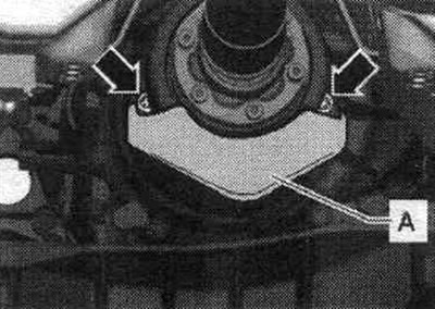
If present, unscrew the "arrow" bolts and remove the heat shield of the propeller shaft "A".

If present, unscrew the «arrow» bolts and remove the heat shield of the propeller shaft «A».


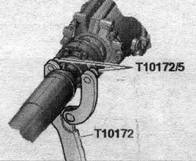
Secure the driveshaft against rotation using the "T10172" stop and the "T10172/5" adapter. For vehicles with a driveshaft mounted on the gearbox side, the rear final drive must be held in a similar manner.

Secure the driveshaft against rotation using the «T10172» stop and the «T10172/5» adapter. For…


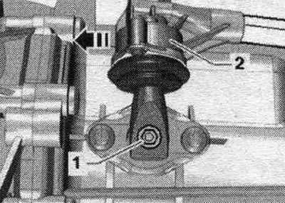
Engage 6th gear by removing shift shaft "1" and shifting gear lever "2" forward in the "direction of the arrow".


Engage 6th gear by removing shift shaft «1» and shifting gear lever «2» forward in the «direction…


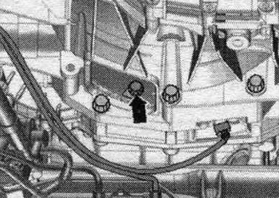
Remove cover "1" under the gearbox "arrow".

Remove cover «1» under the gearbox «arrow».


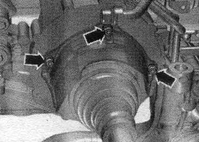
Unscrew the 6 bolts "arrow" of the driven disk, to do this, rotate the clutch module accordingly through 60° in the direction of engine rotation.

Unscrew the 6 bolts «arrow» of the driven disk, to do this, rotate the clutch module accordingly…


The propeller shaft is bolted on the gearbox side: Unscrew the bolts connecting the propeller shaft and gearbox, while holding it from turning using the counter support "T10172" with "T10172/5". Move the propeller shaft toward the rear final drive housing; CV joints are movable in the axial direction. Tie the cardan shaft to the side.


The propeller shaft is inserted from the gearbox side: Remove the propeller shaft.

All


Unscrew the arrow bolts and remove the heat shield of the right drive shaft. For better understanding of the montage. the position is shown with the gearbox removed.

Unscrew the arrow bolts and remove the heat shield of the right drive shaft. For better…


Loosen the arrow bolts and remove the left drive shaft heat shield.

Loosen the arrow bolts and remove the left drive shaft heat shield.


Unscrew the left and right drive shafts from the shafts with the gearbox flange.

Unscrew the left and right drive shafts from the shafts with the gearbox flange.


Unscrew bolt "2" and tie the clutch slave cylinder to the side of the motorcycle. compartment. After removing the working cyl. do not press the clutch pedal. Unscrew nut "1".


Unscrew bolt «2» and tie the clutch slave cylinder to the side of the motorcycle. compartment.…


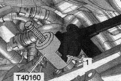
Do not press the shift lever "1" with a crowbar or knock it down with a hammer. The gear shift lever must be removed using the "T40160" puller. Install the "T40160" puller and remove the "1" shift rod.

Do not press the shift lever «1» with a crowbar or knock it down with a hammer. The gear shift…


Unscrew bolt "1", press the mounting plate away from the gearbox and move the "arrow" downwards.

Unscrew bolt «1», press the mounting plate away from the gearbox and move the «arrow» downwards.


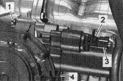
Install the engine and gearbox lift with gearbox mount "T40173" under the gearbox and secure with tension belt "1", as shown in the figure. Unscrew bolt "4" of the starter from the engine side. Disconnect the starter from the gearbox and leave it in the mounting position. position. Do not unscrew starter cables "2" and "3". "Pos. 1" should not be taken into account.


Install the engine and gearbox lift with gearbox mount «T40173» under the gearbox and secure with…


Remove the remaining bolts "7...11" connecting the engine/gearbox. Remove the tunnel crossmember "arrow" bolts.

Remove the remaining bolts «7...11» connecting the engine/gearbox. Remove the tunnel crossmember…


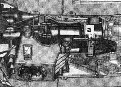
First, lower the CP using a tilting device by dimension "a." Dimension "a" = maximum 100 mm. Preliminarily, lightly tighten the lead screws of the "10-222 A" crosshead.

First, lower the CP using a tilting device by dimension «a.» Dimension «a» = maximum 100 mm.…


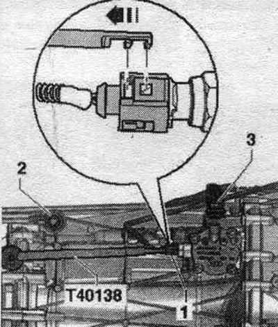
Disconnect electrical connector "1" from gear detection sensor "F208" using puller "T40138" to release the electrical wire. Unscrew bolt "2" of the push rod. Unscrew bolt "3" of the connecting rod. Press the gearbox away from the engine and carefully lower it using a tilting tool.

Disconnect electrical connector «1» from gear detection sensor «F208» using puller «T40138» to…


When replacing a removed gearbox, the following parts must be reinstalled on the new gearbox: if necessary, install the clutch module, the tunnel crossmember with the gearbox cushion and the gearbox support.

[This article was copied from the website «AUDImanual»]
The article was checked by auto expert Timur Bazhenov
This article is available at russian, bulgarian, belarusian, ukrainian, serbian, croatian, romanian, polish, slovak, hungarian

Share information:
Previous articles
Audi A4 B8: Manual gearbox 0B2
Next articles

Gearbox installation for vehicles with a 4-cylinder diesel engine
Gearbox removal — vehicles with a 4-cylinder diesel engine
Gearbox installation — cars with 1.8 l TFSI engine
Removal the gearbox — vehicles with a 1.8 l TFSI engine
Gearbox installation — cars with a 3.2 L FSI engine
Shaft sealing cuffs for gearboxes
Removal and installation the left shaft with flange, clutch…
Removal and installation the differential


Similar articles on other Audi car models:
Engine — removal and installation Audi 80 B3 (1986-1991, petrol)
Engine — removal and installation Audi 100 C3 (1982-1990, diesel)
Removal and installation the lower engine compartment cover Audi A3 Type 8L (1996-2003)
Removal and installation the cylinder head (diesel engine… Audi A6 C5 (1997-2004)
Removal and installation the engine Audi A8 D2 (1994-2002)
Gearbox removal — vehicles with 4-cylinder diesel engine Audi Q5 Type 8R (2008-2017)
Removal and installation the engine Audi A2 (1999-2005)
Link to this page in different formats


Visitor comments

No comments yet


How much will 37 + 16 =


A4(B8, 2007-2015) 
  • General information
  • Operating instructions
  • Power unit
  • Petrol engines 1.8 l
  • Petrol engines 1.8/2.0 l
  • Petrol engines 3.0 l
  • Petrol engines 3.2 l
  • Fuel system (petrol)
  • Diesel engines 2.0 l (CA*)
  • Diesel engines 2.0 l (CJCB)
  • Diesel engines 2.7/3.0 l
  • Diesel engines 3.0 l
  • Fuel system (diesel)
  • Transmission
  • Manual gearbox 0B1
  • Manual gearbox 0B2
  • Manual gearbox 0B3
  • Manual gearbox 0B4
  • Automatic transmission 0B5
  • Automatic transmission 0B6
  • Automatic transmission 0AW
  • All-wheel drive system
  • Chassis
  • Front suspension
  • Rear suspension
  • Brake system
  • Steering system
  • Body
  • Exterior
  • Interior
  • Seats
  • Doors, locks and windows
  • Security system
  • Heating and air conditioning
  • Electrical equipment
  • Audio system
  • Power devices
  • Equipment and devices
  • Lighting and lamps
  • Electrical circuits
 
A4(B7, 2004-2008) 
  • General information
  • Introduction to manual
  • Troubleshooting
  • Operating instructions
  • Maintenance
  • Power unit
  • Petrol engines 2.0 (ALT)
  • Petrol engines 2.0 (TFSI)
  • Petrol engines 1.8 (MPI)
  • Diesel engines
  • Cooling system
  • Air conditioner
  • Fuel and exhaust system
  • Ignition system
  • Starting and charging
  • Transmission
  • Clutch
  • Manual gearbox
  • Automatic gearbox
  • Drive shafts
  • Chassis
  • Brake system
  • Front suspension
  • Rear suspension
  • Steering
  • Body
  • Exterior
  • Interior
  • Electrical equipment
  • Equipment and devices
  • Lighting and signaling
  • Windscreen wipers and washers
  • Electrical diagrams
  • Electrical diagrams (since 2007)
 
A4(B6, 2000-2006) 
  • General information
  • Vehicle Description
  • User manual
  • Maintenance
  • Power unit
  • Gasoline engine
  • Diesel engine
  • Lubrication system
  • Cooling system
  • Supply system
  • Injection system
  • Exhaust system
  • Ignition and control
  • Transmission
  • Gear box
  • Clutch and drive shafts
  • Chassis
  • Brake system
  • Car suspension
  • Steering
  • Body
  • Heating and ventilation
  • Exterior (external elements)
  • Interior (internal elements)
  • Electrical equipment
  • Power devices
  • Lighting and appliances
  • Electrical circuits
 
A4(B6, 2000-2006, petrol) 
  • General information
  • Introduction to the guide
  • Car care
  • Power unit
  • Engine repair
  • Lubrication system
  • Cooling system
  • Injection and control system
  • Ignition system
  • Power and exhaust system
  • Transmission
  • Clutch and drive shafts
  • Car gearbox
  • Chassis
  • Suspension and wheels
  • Steering
  • Brake system
  • Body
  • Interior
  • Exterior
  • Electrical equipment
  • Equipment and devices
  • Lighting and signaling
  • Power devices
  • Electrical circuits
 
A4(B5, 1994-2001) 
  • General information
  • Introduction to the guide
  • Car care
  • Maintenance (gasoline)
  • Maintenance (diesel)
  • Power unit
  • Gasoline engines
  • Diesel engines
  • Engine overhaul
  • Cooling system
  • Fuel injection (gasoline)
  • Fuel system (diesel)
  • Exhaust system
  • Ignition system
  • Transmission
  • Clutch
  • Mechanical gearbox
  • Automatic gearbox
  • Drive shafts
  • Chassis
  • Brake system
  • Car suspension
  • Steering
  • Body
  • Exterior
  • Interior
  • Doors, locks and windows
  • Heating and ventilation
  • Electrical equipment
  • Power devices
  • Equipment and devices
  • Electrical circuits
 
A4(B5, 1994-2001, petrol) 
  • General information
  • Vehicle description
  • Maintenance
  • Power unit
  • Engine repair
  • Turbocharging
  • Exhaust system
  • Cooling system
  • Ignition system
  • Fuel system
  • Motronic injection system
  • MPI and MPFI injection system
  • Transmission
  • Clutch
  • Gearbox and shafts
  • Chassis
  • Steering
  • Car suspension
  • Brake system
  • Wheels and tires
  • Body
  • Heating and ventilation
  • Body parts
  • Electrical equipment
  • Fuses and relays
  • Power devices
  • Lighting and lamps
  • Tools and devices
  • Electrical circuits
 
AudiManual.ru © 2017-2026 · Mobile version · Feedback · Sitemap: EN BG BY UA RS HR RO PL SK HU · Site search · News and articles
80 B2 · 80 B3 petrol · 80 B3 · 80 B4 · 100 C3 diesel · 100 C3 petrol · 100 C3 · 100 C4 petrol · 100 C4 · A3 Type 8L · A4 B5 petrol · A4 B5 · A4 B6 petrol · A4 B6 · A4 B7 · A4 B8 · A6 C4 · A6 C5 · A6 C5 Allroad · A8 D2 · Q5 Type 8R · Q7 Typ 4L · Audi A2 ·
This site uses cookies 🍪. Click the button to accept this fact.