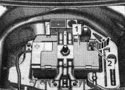
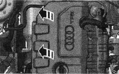
Carefully remove the motor cover. compartment in the "direction of the arrow" with the mounting bolts. Do not remove the engine cover by jerking or moving it to the side.
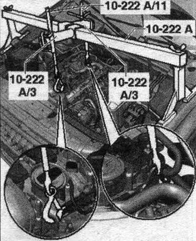
Install the "10-222 A" crossbar with the "10-222 A/3" adapter on the shock absorber strut supports on the left and right, as shown in the figure. Attach the lead screw "10-222 A/11" to the engine suspension eyes.
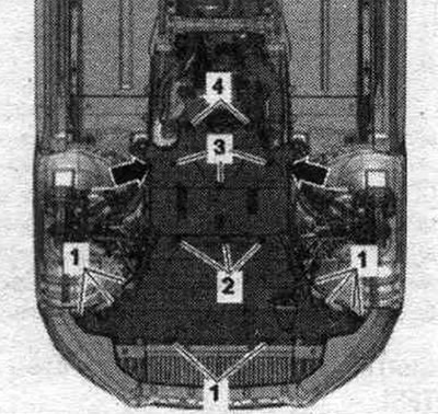
Remove the noise insulation screens by loosening the fastening elements "1...4" and "arrows".
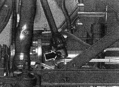
Disconnect the cardan joint from the steering gear only when the front wheels are installed straight. wheels. Do not change the position of the steering wheel or steering gear; if necessary, secure the steering wheel with duct tape. Unscrew the "arrow" bolt of the universal joint. Press the steering gear cardan joint and move it fully upward.
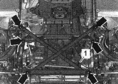
Remove bolt "1" from the power steering hydraulic line. Never lower the vehicle onto its wheels unless the subframe support, steering gear, or subframe cross-joint are properly installed. Unscrew the arrow bolts and remove the subframe spacer crosspiece.
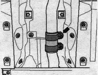
Disconnect the exhaust system by loosening the clamping clamp "arrow". Tie the exhaust pipe to the heat shield under the drive mechanism with wire.
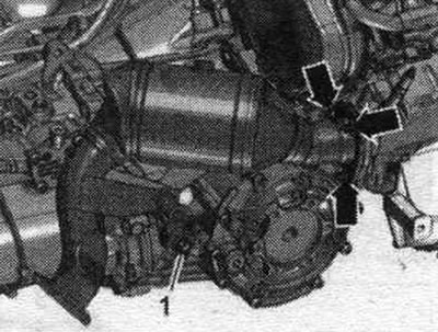
Loosen bolt "1" and move the catalytic converter bracket to the right. "Arrows" should not be taken into account.
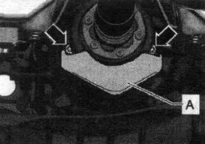
If present, unscrew the "arrow" bolts and remove the heat shield of the propeller shaft "A".
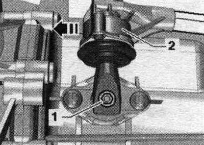
Secure the driveshaft against rotation using the "T10172" stop and the "T10172/5" adapter. For vehicles with a driveshaft mounted on the gearbox side, the rear final drive must be held in a similar manner. Engage 6th gear by removing shift shaft "1" and shifting gear lever "2" forward in the "direction of the arrow".
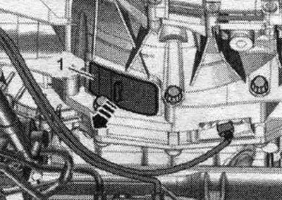
Remove the cover "1" under the gearbox "arrow".
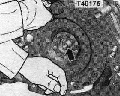
Unscrew the 3 bolts "arrow" of the driven disk, to do this, rotate the clutch module accordingly through 120° in the direction of engine rotation.
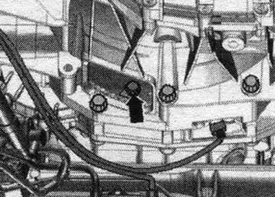
The propeller shaft is bolted on the gearbox side: Unscrew the bolts connecting the propeller shaft and gearbox, while holding it from turning using the counter support "T10172" with "T10172/5". Move the propeller shaft toward the rear final drive housing; CV joints are movable in the axial direction. Tie the cardan shaft to the side.
The propeller shaft is inserted from the gearbox side: Remove the propeller shaft.
All
Unscrew the arrow bolts and remove the heat shield of the right drive shaft.
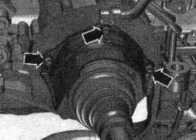
Unscrew the left and right drive shafts from the shafts with the gearbox flange.
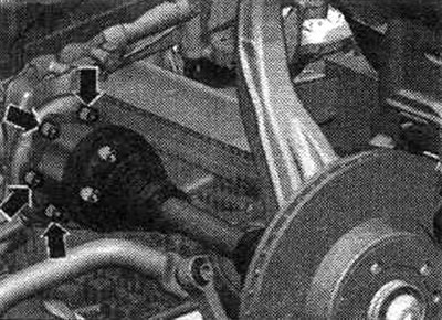
Vehicles with start-stop system: Disconnect the electrical connector of the neutral position sensor of the gearbox "G701" "1" and release the cable.
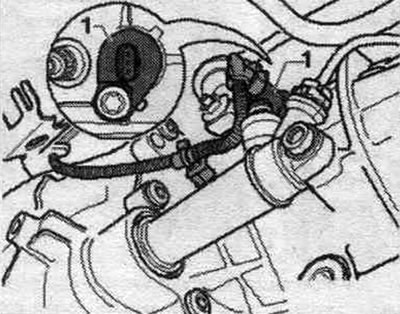
All
Unscrew bolt "2" and tie the clutch slave cylinder to the side of the motorcycle. compartment. After removing the working cyl. do not press the clutch pedal. Unscrew nut "1".
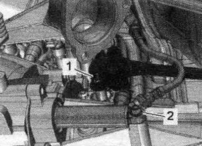
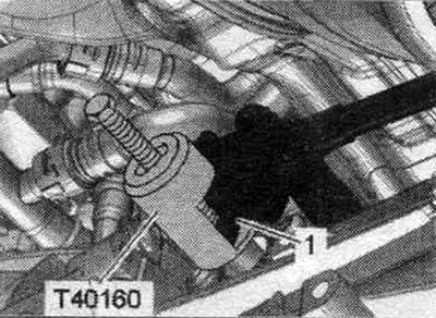
Do not press the shift lever "1" with a crowbar or knock it down with a hammer. The gear shift lever must be removed using the "T40160" puller. Install the "T40160" puller and remove the "1" shift rod.
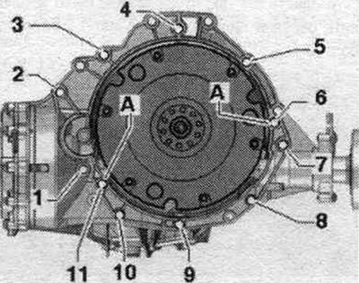
Remove bolts "8...11" connecting the engine to the gearbox. Bolts "1...7" securing the engine to the gearbox are removed and installed from below with the gearbox lowered.
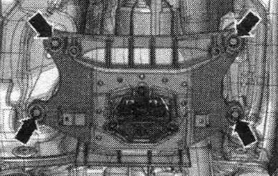
Install the engine and gearbox lift with gearbox mount "T40173" under the gearbox and secure with tension belt "1", as shown in the figure. When fixing the tension belt, make sure that the electrical wires on the gearbox are not pinched. Unscrew the tunnel cross member arrow bolts.
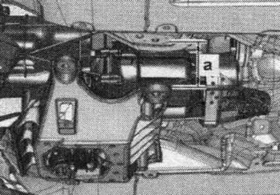
First, lower the gearbox using a tilting device by dimension "a." Dimension "a" = maximum 80 mm. Preliminarily, lightly tighten the lead screws of the "10-222 A" crossmember. To access the threaded pins with the vehicle raised, use the "VAS 5085" stepladder.
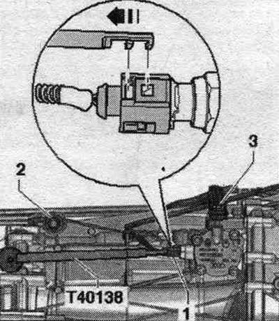
Disconnect electrical connector "1" from gear detection sensor "F208" using puller "T40138" to release the electrical wire. Unscrew bolt "2" of the push rod. Unscrew bolt "3" of the connecting rod.
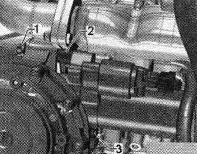
Unscrew bolt "3" of the starter from the engine side. Unscrew bolt "1". Remove spacer sleeve "2" between the starter and gearbox. Disconnect the starter from the gearbox and leave it in the mounting position. position. There is no need to disconnect the starter cables. Remove the remaining engine-to-gearbox mounting bolts. Lift the gearbox away from the engine and carefully lower it using a tilting tool.
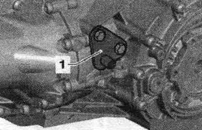
When replacing a removed gearbox, the following parts must be reinstalled on the new gearbox. Bracket "1" of the support bar of the system. exhaust. Tunnel crossmember with gearbox cushion and gearbox support.
If necessary, remove the clutch module.