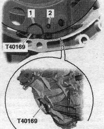
Install the clutch module if necessary. Before connecting the engine and gearbox, carry out the following preparatory actions. Insert mont. device "T40169" from below into the gearbox housing and install the clutch module as shown in the figure. Mounting tool "T40169" should fit into semicircular groove "1" and additionally into inspection hole "2." To locate the inspection hole, it is necessary to rotate the clutch module. Insert mounting bolts. devices into the hole on the gearbox housing.
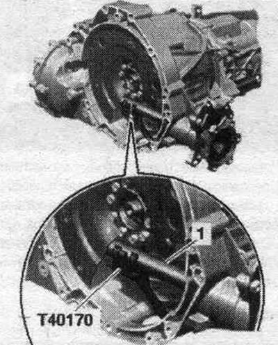
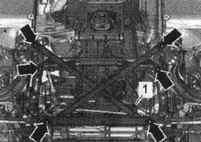
Install the "T40170" transport protection from below under the gearbox housing and attach it to the shaft with flange "1".
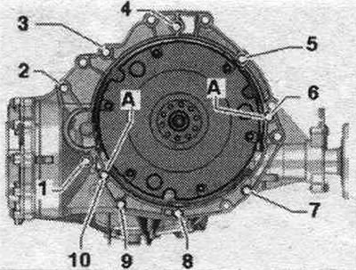
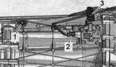
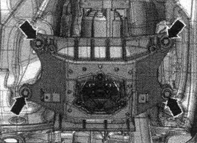
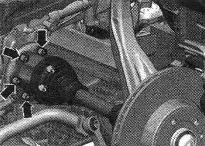
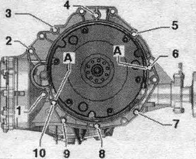
Make sure that the guide bushings "A" for aligning the engine and gearbox in the cylinder block are present; if necessary, insert the missing bushings. If necessary, check for reuse and mark the aluminum bolts "2...10" connecting the engine and gearbox.
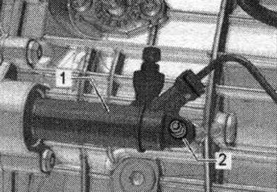
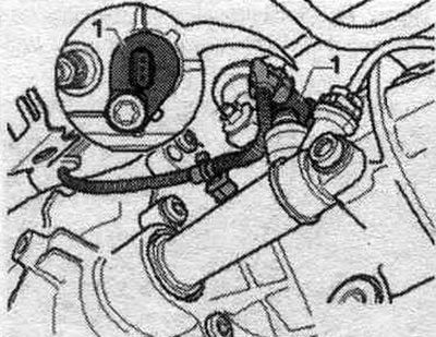
Raise the gearbox so that clutch slave cylinder "1" can be installed. Tighten bolt "2".
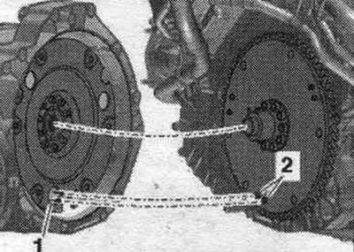
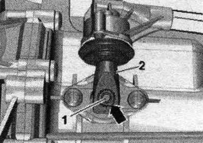
The next step is only necessary if the driven disc with locking pin "2" is installed. Additionally, align the position of the driven disc in relation to the clutch module so that locking pins "2" (if available) on the driven disk could enter the large holes "1" on the clutch module. If the retaining pins of the driven disk "2" do not enter the holes of the clutch module "1", this can lead to serious problems in the operation of the clutch.
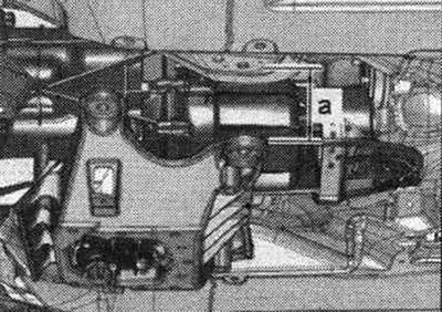
Place the engine against the transmission and tighten bolts "7...10" connecting the engine to the transmission. Raise the transmission with a powertrain lift until gap "a" between the tunnel crossmember and the body is reached. Size "a" = not less than 80 mm.
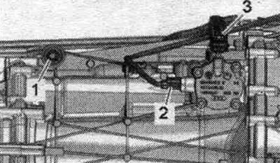
Install the starter and hand tighten bolt "3" on the engine side. Insert spacer sleeve "2" between the starter and gearbox, insert and screw in bolt "1". Tighten starter bolts "1" and "3". Install bolt "1" and spacer sleeve "2" on top, on the removed front wall of the water drain box. Use the stepladder "VAS 5085".
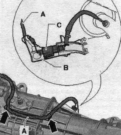
Attach bracket "B" with plug connector "C" of exhaust gas temperature sensor 4 "G648" to the gearbox. Attach wire "A" to the gearbox "arrows".
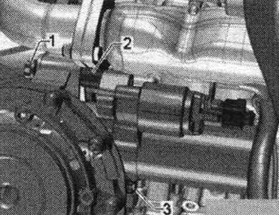
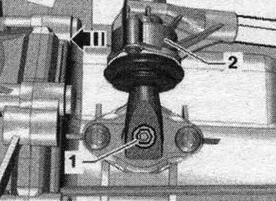
Tighten the shift fork rod "1". Attach the connector "2" of the gear detection sensor "F208".
Install the gearshift lever as follows: gearshift lever "2" can be installed on shift shaft "1" in only one position (the notch in the gear ring "arrow"). Tighten gearshift lever "2".
Vehicles with start-stop system: Connect the connector of the neutral position sensor of the gearbox "G701" "1".
All
Loosen the lead screws "10-222 A/11". Continue raising the gearbox and tighten the bolts of the tunnel crossmember "arrow". Remove the engine and gearbox lift with the "T40173" gearbox mount from under the gearbox. Remove the "10-222 A" crossmember.
Tighten the remaining bolts "3...6" connecting the engine/gearbox. Bolts "3" and "5" additionally secure the line brackets.
Screw the connecting rod "3" from above, through the removed front wall of the water drainage box. Pos. "2" and "3" do not take into account.
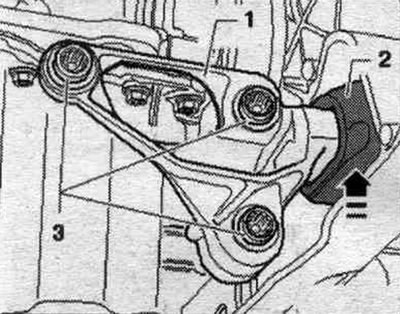
Raise the front engine mount "1" up until it touches the crossmember in the direction of the arrow. The buffer "2" should be flush with the crossmember without any gap or tension. Then tighten bolts "3" to the specified tightening torque.
Bolt the left and right drive shafts to the shafts with the gearbox flange.
Install the driveshaft or bolt it to the gearbox. Secure the driveshaft. To do this, install the support "T10172" with "T10172/5" on the bolts securing the propeller shaft to the gearbox or rear final drive.
Bolt tightening sequence - clutch module to driven disc
Remove transport lock "T40170" and mounting tool "T40169". Engage 6th gear by removing shift shaft "1" and shifting gearbox lever "2" forward in the direction of the arrow.
The next stage of work is absolutely necessary to ensure uniform contact with the driven disk without distortion. Rotate both fronts. wheels in one direction so that the clutch module makes 1 full revolution. The inspection hole "arrow" should be visible again in the recess of the gearbox housing.
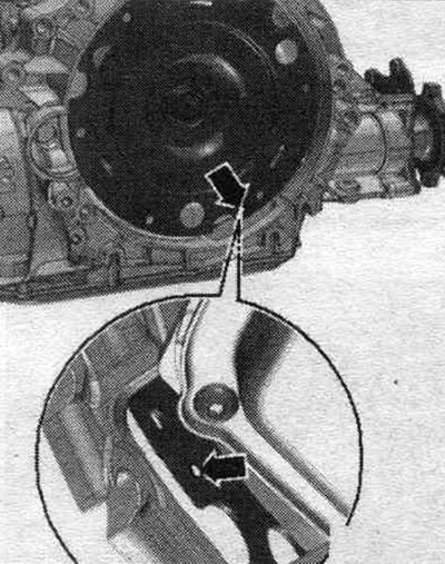
Tighten the clutch module bolts to the driven disc as follows. Use new bolts. Tighten the bolts with a 16 mm ring spanner "VAG 1332/14". Tighten the first bolt "arrow" by hand (2 Nm). Turn the clutch module using the front. wheels 120° in the direction of engine rotation and tighten bolt 2 by hand (2 Nm). Turn the clutch module again 120° in the direction of engine rotation. Then screw in and tighten the 3rd bolt. Now tighten the 2 remaining bolts. Installation in reverse order. Bolt the universal joint to the steering gear.
Install the drive shaft heat shield.
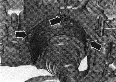
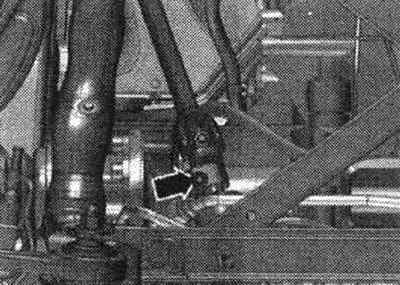
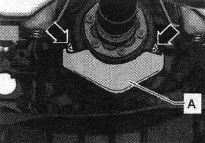
If present, install the heat shield for the driveshaft "A" and tighten the "arrow" bolts to 25 Nm. Assemble the system. exhaust and align without tension.
Install the subframe crosspiece. Install the front wall of the water drainage box. If present, install a spacer. If necessary, install the air casing. filter. Fill with coolant. Check the oil level in the manual transmission. Install noise insulation screens. Pay attention to the battery installation work.
Tightening torques (Nm)
| Bolts and nuts | M6 | 9 |
| M7 | 15 | |
| M8 | 20 | |
| M10 | 40 | |
| M12 | 65 |
PTO shaft heat shield - tightening torque
Tighten the drive shaft heat shield arrow bolts to 23 Nm.
Fastening the engine to the manual transmission
| Pos. | Bolt | Nm |
| 1 (1) | M10 x 50 (2) | 65 |
| 2 (1) | M12 x 100 (3), (4) | 30 + 90° |
| 3 (5), 6 | M12 x 75 (3), (4) | 30 + 90° |
| 4, 5 (5) | M12 x 120 (3), (4) | 30 + 90° |
| 7...9 | M10 x 75 (3), (4) | 15 + 90° |
| 10 | M12 x 50 (3), (4) | 30 + 90° |
| A | Centering bushings | |
(1) Additionally secures the starter.
(2) Bolt strength 10.9; this steel bolt can be used repeatedly.
(3) Audi A4 up to ID. numbers 8K-9-066499: replace aluminum bolts.
(4) Audi A4 with ID. numbers 8K-9-066500: use aluminum bolts twice.
(5) Additionally secures the electrical cable bracket.
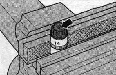
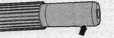
Audi A4 with identification. part numbers 8K-9-066500: Aluminum bolts "2...11" may be used no more than twice. Therefore, after the first use, mark these bolts with two notches "X" and "arrow" using a cutter. To avoid damaging the bolts during notching, do not clamp them in a vice. Insert the bolt as shown in the illustration into the 14 mm socket using a 1/2-inch drive, which can then be clamped in a vice. Do not reuse bolts marked with "X".