
Table of contents: LuK clutch repair ↓ Removal and installation the clutch… ↓
LuK clutch repair
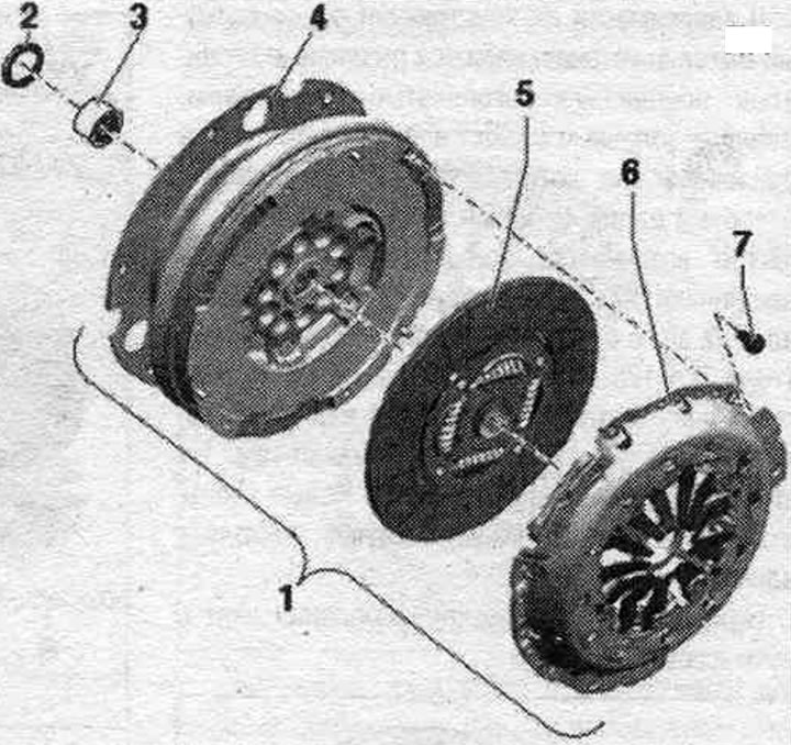
1. Clutch module.
2. Lip seal for dual mass flywheel.
3. Needle bearing for dual mass flywheel: check and replace if necessary. If the drive shaft is damaged, always replace the needle bearing. Depending on the design, needle bearings may have a full complement of rollers or needle bearings with every fourth roller missing. This is not a defect in the needle bearing.
4. Dual mass flywheel with transfer plate: ensure that the centering pins are securely installed; there should be no grooves, oil or grease on the mating surface of the clutch lining.
5. Clutch driven disc; installation position: the inscription "KP side" faces the pressure plate; if available: damping package (coil springs) facing the pressure plate.
6. SAC support plate: check the ends of the diaphragm spring; check the pressure plate for warpage; check the return spring and riveted joints; there should be no grooves, oil or grease on the mating surface of the clutch lining.
7. Bolt: 22 Nm and 90° turn; always subject to replacement; for fastening the pressure plate on the dual mass flywheel; loosen or tighten according to installation instructions.
Removal and installation the clutch disc and pressure plate manufacturer LuK
Remove the clutch module.
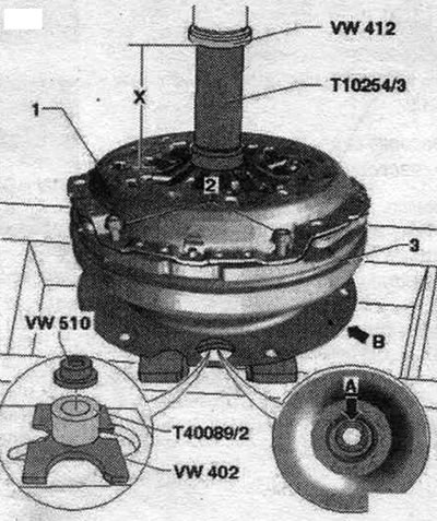
Clutch pressure plate. Risk of damage to the pressure plate and dual mass flywheel. Pressure plate "1" may only be removed and installed in a pre-compressed state. Pre-compressed pressure plates are deformed when bolts "2" are loosened or tightened, which leads to jerking when starting off. To compress pressure plate "1" using a hydraulic press, dual-mass flywheel "3" may only be supported by the sliding washer "arrow A." Supporting the dual-mass flywheel against the transfer plate "arrow B" will damage it (deformation). In this case, it is necessary to replace the dual mass flywheel. Install the clutch module so that the pressure plate "VW 510" is adjacent to the sliding washer "arrow A" in the dual mass flywheel. Install mont. device "T10254/3" on the spring tongues of the pressure plate "1" and press on them using a press. Compression stroke - dimension "x" 8...9 mm. Unscrew all 6 bolts "2" and release the press. Remove pressure plate "1" and clutch driven disc.
Installation
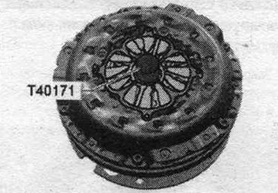
Installation in reverse order. Check the clutch pressure plate for deformation. When replacing only the pressure plate, the pressure plate adjusting ring must be pulled back to the stop before installation. Center the clutch driven disc using the centering mandrel "T40171". Clutch disc mounting position: damping package (coil springs) or an inscription "Getriebeseite" (side of the checkpoint) must be facing the CP.
Install the pressure plate onto the locating pins. Install the clutch module so that the pressure plate "VW 510" is adjacent to the sliding washer "arrow A" in the dual mass flywheel.
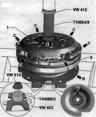
Clutch pressure plate. Risk of damage to the dual mass flywheel. To compress pressure plate "1" using a hydraulic press, dual-mass flywheel "3" may only be supported by the sliding washer "arrow A." Supporting the dual-mass flywheel against the transfer plate "arrow B" will damage it (deformation). In this case, it is necessary to replace the dual mass flywheel. Install mont. device "T10254/3" over the centering mandrel "T40171". Apply pressure with the press until the pressure plate "1" lies against the dual-mass flywheel "3" "arrows C". Screw in all 6 bolts "2" one after the other and tighten to the specified torque. Release the pressure from the press. Install the clutch module.
Adjusting ring on pressure plate only produced by LuK
When installing a new clutch disc together with a used pressure plate, it is necessary to move the pressure plate adjusting ring back as far as it will go. If the pressure plate adjusting ring is not set to its original position, the plate will operate with less clamping force, which will lead to increased wear of the clutch, especially the clutch disc (clutch slippage). If the clutch disc is not being replaced, the position of the adjusting ring should not be changed. The adjusting ring of the new pressure plates is already in its original position.
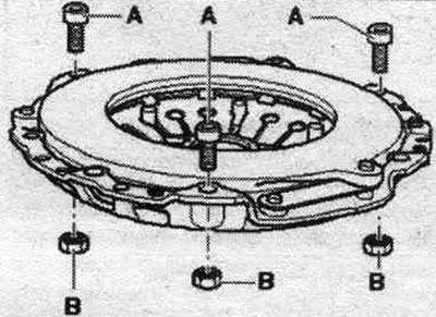
Install 3 mounting bolts "A" at a 120° angle into the pressure plate mounting holes as shown in the figure. Screw 3 M8 nuts "B" onto bolts "A" and lightly tighten the nuts.
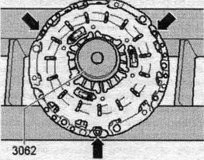
Place the pressure plate on the press so that it rests only on the heads of the three "arrow" bolts. Install the "3062" press washer in the center of the pressure plate.
The operation described below must be carried out without using force, otherwise the forks of the adjusting ring may break.
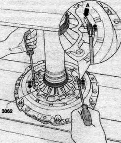
Place 2 screwdrivers against the forks of the adjusting ring. Lower the press just enough to allow the adjustment ring to be moved. Using both screwdrivers, evenly rotate the adjusting ring "in the direction of the arrow" until the ring reaches the stop "arrow A." Holding the adjusting ring in this position, lift the press. At this point, the adjustment ring will be fixed.