
Repair Chevrolet Repair Toyota Repair Honda Repair AvtoVAZ Repair Mercedes-Benz Repair BMW Repair Opel
Home  |  Contacts  |  Sitemap  |    
English Русский
Български
Беларускі
Український
Српски
Hrvatski
Română
Polski
Slovenský
Magyar
AudiManual.ru


  • AUDI 80
  • AUDI 100
  • AUDI A3
  • AUDI A4
  • AUDI A6
  • AUDI A8
  • AUDI Q
  • OTHER
  • ARTICLES
B8 (2007-2015) B7 (2004-2008) B6 (2000-2006) B6 (2000-2006, petrol) B5 (1994-2001) B5 (1994-2001, petrol)

Hydraulic clutch system — removal and installation (Audi A4 B8)

  • Home
  • Audi A4
  • B8 (2007-2015)
  • Transmission
  • Manual gearbox 0B1
  • Hydraulic clutch system — removal and installation
            0
Table of contents: Hydraulic clutch system ↓ Disconnecting and connecting the… ↓ Removal and installation the main… ↓ Removal and installation of cyl.… ↓

Hydraulic clutch system


Follow the instructions for removing and installing the clutch master and slave cylinders.
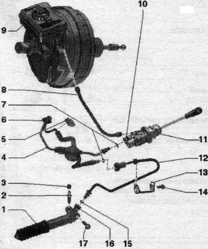

1. Clutch slave cylinder: After removing, do not press the clutch pedal; after working on the…

1. Clutch slave cylinder: After removing, do not press the clutch pedal; after working on the hydraulic clutch drive, bleed the clutch drive; brake impact. liquids on the gearbox are not allowed.
2. Bleed nipple: 5.5 Nm; follow the procedure when pumping; a broken bleed nipple can be unscrewed with an internal hex key (3 mm).
3. Cap.
4. Pipe-hose line: with frequency modulator.
5. Mounting clip.
6. Nozzle.
7. O-rings: Replace if damaged; install by wetting the brake. liquid.
8. Feed hose: for main cyl. clutch; with built-in sealing nozzles; in case of damaged seals. replace the feed hose on the nozzles.
9. Brake reservoir. liquids.
10. Locking clamp: To remove the hose line, pull it out as far as it will go.
11. Clutch master cylinder: after working on the hydraulic clutch drive, bleed the clutch drive.
12. Pipeline.
13. Pipeline holder: attached to the control panel.
14. Bolt: 20 Nm.
15. Sealing ring: replace if damaged; install by wetting the brake. liquid.
16. Locking clamp: To remove the hose line, pull it out as far as it will go.
17. Bolt: clutch slave cylinder to gearbox; 20 Nm.


Disconnecting and connecting the pipe and hose line


Unlock the locking bracket "A" with a screwdriver and pull it out until it stops. Disconnect the pipe and hose line.
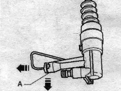
Unlock the locking bracket «A» with a screwdriver and pull it out until it stops. Disconnect the…


Connection


If damaged, replace the seal. ring. Press the locking clip "A" until it stops. Insert the pipe-hose line into the branch pipe until it clicks into place. To check, pull the pipe-hose line.

Removal and installation the main cyl. clutch


Disconnect the ground wire "2" from the battery terminal.
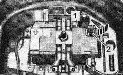
Disconnect the ground wire «2» from the battery terminal.


Remove the junction box.
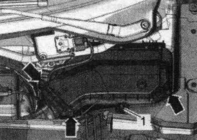
Remove the junction box.


Clamp the brake fluid supply hose. fluid "2" to the brake reservoir. fluid using the hose clamp "3094" on the clutch master cylinder "1", remove and plug the hose. To remove the locking bracket "3", you need to unlock it with a screwdriver and pull it out until it stops. Disconnect the pipe and hose line "4". Connector "pos. 5" remains connected for now.
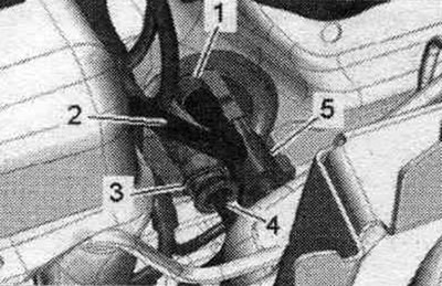


Clamp the brake fluid supply hose. fluid «2» to the brake reservoir. fluid using the hose clamp…


Remove the servo spring. Remove locking pin "1" from clutch pedal "3". Ignore pos. 2- and -arrows A, B-.
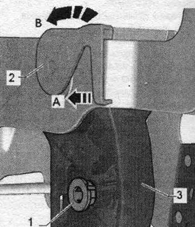
Remove the servo spring. Remove locking pin «1» from clutch pedal «3». Ignore pos. 2- and -arrows…


Unlock the clutch master cylinder using the open-end spanner SW 32 "3355" in the "direction of the arrow".
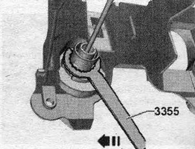
Unlock the clutch master cylinder using the open-end spanner SW 32 «3355» in the «direction of the…


Remove clutch master cylinder "1" and route it through the engine wiring harness opening. Unlock and disconnect plug connection "5".


Installation


If damaged, replace the seal. ring. Connect the plug connection "5". Install the clutch master cylinder "1". Route the clutch master cylinder into the footwell "direction of arrow A". In doing so, secure it with the 32 mm open-end wrench "3355" in the "direction of arrow B".
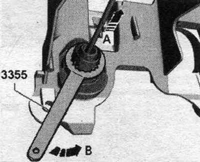
If damaged, replace the seal. ring. Connect the plug connection «5». Install the clutch master…


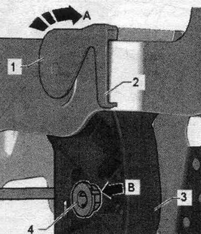
Install locking pin "4". The protrusion on the pin "arrow B" should enter the groove on the clutch pedal. "Pos. 1, 2, 3" and "arrow A" are not taken into account. Install the servo spring.
Install locking pin «4». The protrusion on the pin «arrow B» should enter the groove on the clutch…


Press the locking clip "3" until it stops. Insert the pipe-hose line "4" into the clutch slave cylinder until it clicks into place. To check, pull the pipe-hose line. Push on the brake supply hose. fluid "2" until it stops. Remove hose clamp "3094". Bleed air from the clutch assembly. Installation in reverse order. Install the junction box. Take into account the measures required after connecting the battery.


Removal and installation of cyl. clutch booster


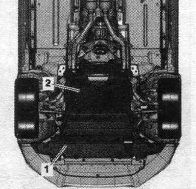
Follow the instructions for removing and installing the clutch master and slave cylinders. Brake hit. liquids on the gearbox are not allowed. If necessary, clean the gearbox housing. If present, remove the rear noise insulation "2".
Follow the instructions for removing and installing the clutch master and slave cylinders. Brake…


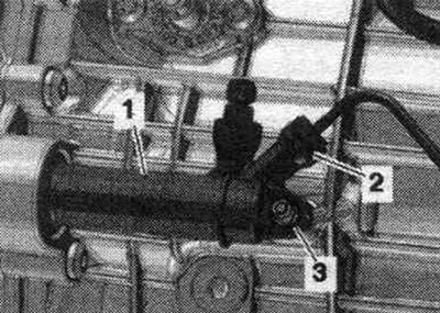
To remove the locking bracket "2", you need to unlock it with a screwdriver and pull it out until it stops. Remove the hose line from the working cylinder. clutch and close it. Unscrew bolt "3", remove clutch slave cylinder "1" back.
To remove the locking bracket «2», you need to unlock it with a screwdriver and pull it out until…


Installation


Installation in reverse order. If damaged, replace the seal. ring. When the working cylinder is warped. during installation, there is a risk that the push rod will pass the clutch release lever. Press down on the clutch slave cylinder "1" until the mounting bolt "3" can be easily installed. Press the locking clip "2" until it stops. Insert the hose/pipe line into the clutch slave cylinder until it clicks into place. To check, pull the pipe-hose line. Remove air from the clutch assembly. Install (if available) rear noise insulation screen.

(The original version of the article is posted on the website AUDIMANUAL.RU)
The article was checked by auto expert Timur Bazhenov
This article is available at russian, bulgarian, belarusian, ukrainian, serbian, croatian, romanian, polish, slovak, hungarian

Share information:
Previous articles
Audi A4 B8: Manual gearbox 0B1
Next articles

Clutch drive repair
Checkpoint markings and location at the checkpoint
Clutch module general information
Sachs clutch repair
LuK clutch repair
Replacement of the dual mass flywheel needle bearing…


Similar articles on other Audi car models:
Clutch hydraulic system — bleeding Audi 80 B3 (1986-1991, petrol)
Clutch hydraulic system — bleeding Audi 100 C3 (1982-1990, diesel)
Bleeding air from the clutch hydraulic system Audi A3 Type 8L (1996-2003)
Bleeding the hydraulic system of the clutch release drive Audi A6 C4 (1994-1997)
Bleeding the hydraulic clutch drive Audi A8 D2 (1994-2002)
Hydraulic clutch system Audi Q5 Type 8R (2008-2017)
Hydraulic clutch drive system Audi A2 (1999-2005)
Link to this page in different formats


Visitor comments

No comments yet


How much will 23 + 30 =


A4(B8, 2007-2015) 
  • General information
  • Operating instructions
  • Power unit
  • Petrol engines 1.8 l
  • Petrol engines 1.8/2.0 l
  • Petrol engines 3.0 l
  • Petrol engines 3.2 l
  • Fuel system (petrol)
  • Diesel engines 2.0 l (CA*)
  • Diesel engines 2.0 l (CJCB)
  • Diesel engines 2.7/3.0 l
  • Diesel engines 3.0 l
  • Fuel system (diesel)
  • Transmission
  • Manual gearbox 0B1
  • Manual gearbox 0B2
  • Manual gearbox 0B3
  • Manual gearbox 0B4
  • Automatic transmission 0B5
  • Automatic transmission 0B6
  • Automatic transmission 0AW
  • All-wheel drive system
  • Chassis
  • Front suspension
  • Rear suspension
  • Brake system
  • Steering system
  • Body
  • Exterior
  • Interior
  • Seats
  • Doors, locks and windows
  • Security system
  • Heating and air conditioning
  • Electrical equipment
  • Audio system
  • Power devices
  • Equipment and devices
  • Lighting and lamps
  • Electrical circuits
 
A4(B7, 2004-2008) 
  • General information
  • Introduction to manual
  • Troubleshooting
  • Operating instructions
  • Maintenance
  • Power unit
  • Petrol engines 2.0 (ALT)
  • Petrol engines 2.0 (TFSI)
  • Petrol engines 1.8 (MPI)
  • Diesel engines
  • Cooling system
  • Air conditioner
  • Fuel and exhaust system
  • Ignition system
  • Starting and charging
  • Transmission
  • Clutch
  • Manual gearbox
  • Automatic gearbox
  • Drive shafts
  • Chassis
  • Brake system
  • Front suspension
  • Rear suspension
  • Steering
  • Body
  • Exterior
  • Interior
  • Electrical equipment
  • Equipment and devices
  • Lighting and signaling
  • Windscreen wipers and washers
  • Electrical diagrams
  • Electrical diagrams (since 2007)
 
A4(B6, 2000-2006) 
  • General information
  • Vehicle Description
  • User manual
  • Maintenance
  • Power unit
  • Gasoline engine
  • Diesel engine
  • Lubrication system
  • Cooling system
  • Supply system
  • Injection system
  • Exhaust system
  • Ignition and control
  • Transmission
  • Gear box
  • Clutch and drive shafts
  • Chassis
  • Brake system
  • Car suspension
  • Steering
  • Body
  • Heating and ventilation
  • Exterior (external elements)
  • Interior (internal elements)
  • Electrical equipment
  • Power devices
  • Lighting and appliances
  • Electrical circuits
 
A4(B6, 2000-2006, petrol) 
  • General information
  • Introduction to the guide
  • Car care
  • Power unit
  • Engine repair
  • Lubrication system
  • Cooling system
  • Injection and control system
  • Ignition system
  • Power and exhaust system
  • Transmission
  • Clutch and drive shafts
  • Car gearbox
  • Chassis
  • Suspension and wheels
  • Steering
  • Brake system
  • Body
  • Interior
  • Exterior
  • Electrical equipment
  • Equipment and devices
  • Lighting and signaling
  • Power devices
  • Electrical circuits
 
A4(B5, 1994-2001) 
  • General information
  • Introduction to the guide
  • Car care
  • Maintenance (gasoline)
  • Maintenance (diesel)
  • Power unit
  • Gasoline engines
  • Diesel engines
  • Engine overhaul
  • Cooling system
  • Fuel injection (gasoline)
  • Fuel system (diesel)
  • Exhaust system
  • Ignition system
  • Transmission
  • Clutch
  • Mechanical gearbox
  • Automatic gearbox
  • Drive shafts
  • Chassis
  • Brake system
  • Car suspension
  • Steering
  • Body
  • Exterior
  • Interior
  • Doors, locks and windows
  • Heating and ventilation
  • Electrical equipment
  • Power devices
  • Equipment and devices
  • Electrical circuits
 
A4(B5, 1994-2001, petrol) 
  • General information
  • Vehicle description
  • Maintenance
  • Power unit
  • Engine repair
  • Turbocharging
  • Exhaust system
  • Cooling system
  • Ignition system
  • Fuel system
  • Motronic injection system
  • MPI and MPFI injection system
  • Transmission
  • Clutch
  • Gearbox and shafts
  • Chassis
  • Steering
  • Car suspension
  • Brake system
  • Wheels and tires
  • Body
  • Heating and ventilation
  • Body parts
  • Electrical equipment
  • Fuses and relays
  • Power devices
  • Lighting and lamps
  • Tools and devices
  • Electrical circuits
 
AudiManual.ru © 2017-2026 · Mobile version · Feedback · Sitemap: EN BG BY UA RS HR RO PL SK HU · Site search · News and articles
80 B2 · 80 B3 petrol · 80 B3 · 80 B4 · 100 C3 diesel · 100 C3 petrol · 100 C3 · 100 C4 petrol · 100 C4 · A3 Type 8L · A4 B5 petrol · A4 B5 · A4 B6 petrol · A4 B6 · A4 B7 · A4 B8 · A6 C4 · A6 C5 · A6 C5 Allroad · A8 D2 · Q5 Type 8R · Q7 Typ 4L · Audi A2 ·
This site uses cookies 🍪. Click the button to accept this fact.