
Table of contents: Gear shift mechanism ↓ Removal and installation the gear… ↓
Gear shift mechanism
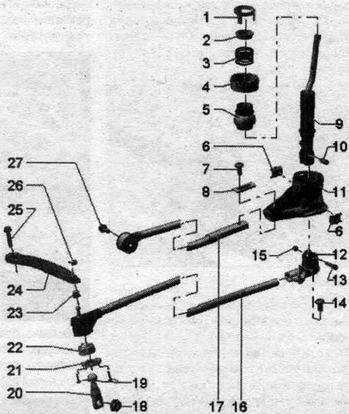
1. Retaining ring: To remove, remove the ball.
2. Expansion sleeve.
3. Pressure spring.
4. Ball guide: Do not lubricate.
5. Ball: Do not lubricate.
6. Sound insulation: do not lubricate.
7. Bolt: 23 Nm.
8. Clamping plate: Do not lubricate.
9. Selector: bend looks back; if necessary, lubricate the plunger guide and shift lever stops; lubricate the mating surfaces of the hinge.
10. Spacer tube: lubricate the outer perimeter.
11. Shift lever bearing: Do not lubricate.
12. Joint: between the rod and the shift lever; lubricate the mating surfaces of the shift lever.
13. Bolt for hinge.
14. Bolt: 23 Nm.
15. Nut: 10 Nm.
16. Shift rod.
17. Push rod: with bolt and washer.
18. Nut: 20 Nm; replace.
19. Bolt: 4 Nm.
20. Gear shift lever: install so that the splines on the shift shaft align. Risk of damage to the gearshift shaft. Do not use a crowbar to force the shift lever or hammer it on. The gear shift lever must be removed only using the "T40160" puller.
21. Sealing cuff.
22. Ball joint: If necessary, lubricate the bearing surface of the gear engagement lever.
23. Support sleeve: to remove, remove the protective bracket.
24. Connecting rod: to remove, remove the protective bracket.
25. Bolt: 20 Nm.
26. Locking clamp.
27. Bolt: 20 Nm.
Removal and installation the gear shift drive
Turn off the ignition. Remove the gearshift lever handle with the gearshift lever boot. Remove the climate control and display unit.
Remove the multimedia system control panel. "E380".
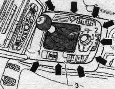
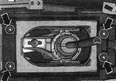
Remove the front ashtray "1".
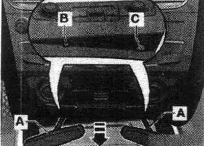
Remove the sound insulation above the gear shift drive. Unscrew the "arrow" nuts.
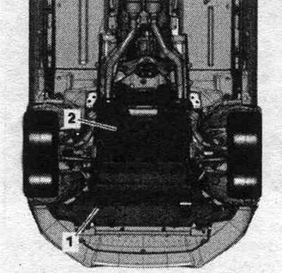
Remove the rear noise insulation screen "2". Vehicles with a diesel engine: Additionally remove the front noise insulation "1".
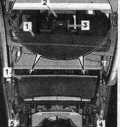
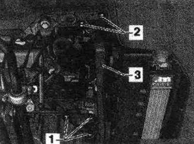
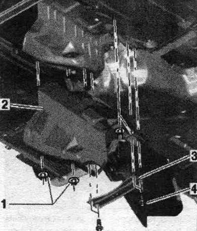
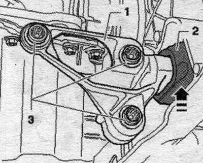
Remove the front support from the engine by unscrewing bolts "1". Ignore "Pos. 2, 3".
All
Separate the system. exhaust gas outlet from the "arrow" bushing.
Unscrew bolts "4" and remove crossmember "3". Unscrew nuts "1" and remove heat shield "2".
Place the lift stand with the "T10337" transmission support mounted under the transmission. Raise the transmission slightly using the lift.
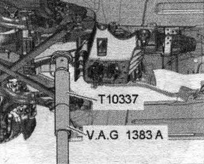
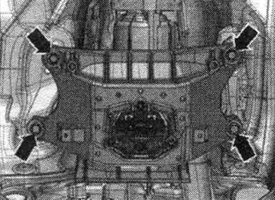
Unscrew the bolts of the tunnel cross member "arrow".
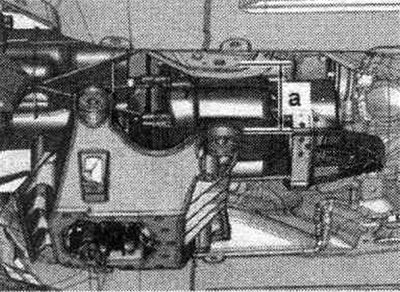
Lower the transmission using a lift by dimension "a". Dimension "a" = maximum 80 mm.
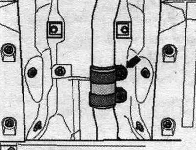
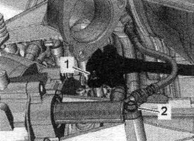
Unscrew bolt "1" of the push rod and "3" of the connecting rod. "Pos. 2" should not be taken into account.
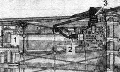
Unscrew nut "1". Ignore "Pos. 2".
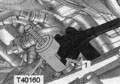
Risk of damage to the gearshift shaft. Do not press on the "1" shift lever with a crowbar or hammer. The gearshift lever must be removed using the T40160 puller. Install the T40160 puller and remove the gearshift lever. Pull the gear shift mechanism downwards.
Installation
Installation in reverse order. Replace the seals and self-locking nuts with new ones. Install the tunnel crossbar.
Diesel vehicles: Raise the front engine mount "1" up until it touches the crossmember in the direction of the arrow. The bumper "2" should be flush with the crossmember without any play or tension. Then tighten bolts "3" to the specified tightening torque.
All
Install a heat shield under the drive mechanism. Assemble the system. exhaust and align without tension. Install sound insulation. Install the gear shift drive. Install the multimedia system control panel. "E380". Install the climate control and display unit.