
Repair Chevrolet Repair Toyota Repair Honda Repair AvtoVAZ Repair Mercedes-Benz Repair BMW Repair Opel
Home  |  Contacts  |  Sitemap  |    
English Русский
Български
Беларускі
Український
Српски
Hrvatski
Română
Polski
Slovenský
Magyar
AudiManual.ru


  • AUDI 80
  • AUDI 100
  • AUDI A3
  • AUDI A4
  • AUDI A6
  • AUDI A8
  • AUDI Q
  • OTHER
  • ARTICLES
B8 (2007-2015) B7 (2004-2008) B6 (2000-2006) B6 (2000-2006, petrol) B5 (1994-2001) B5 (1994-2001, petrol)

Engine installation (Audi A4 B8)

  • Home
  • Audi A4
  • B8 (2007-2015)
  • Power unit
  • Diesel engines 2.7/3.0 l
  • Engine installation
            0

Tightening torques (Nm)


Bolts and nutsM69
M715
M820
M1040
M1265

Ground bolt to the body near the shock absorber cup
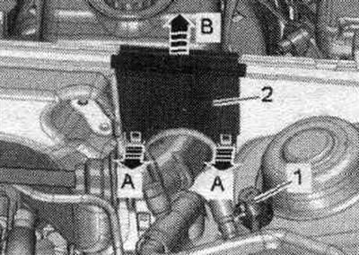


Tighten ground bolt «1» to 9 Nm.

Tighten ground bolt "1" to 9 Nm.


Ground wires to the side members
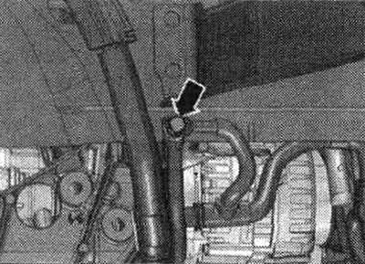


Tighten the arrow nut to a torque of 9 Nm.

Tighten the arrow nut to a torque of 9 Nm.


Engine for the multitronic 0AW gearbox
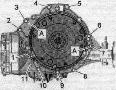


Engine for the multitronic 0AW gearbox


Pos.BoltNm
1M10x50(1)65
2...6M12x100 (2), (3)30 + 90°
7M12x125 (2), (3)30 + 90°
8, 11M 10x60 (2), (3)15 + 90°
9, 10M10x95 (2), (3)15 + 90°
ACentering bushings


(1) Bolt strength class 10.9. Steel bolt can be used repeatedly.

(2) Up to identification number 8K-9-066499: Replace aluminum bolts.

(3) From ID number 8K-9-066500: Aluminum bolts are used twice.


Aluminum bolts "2...11" may be used no more than 2 times. Therefore, after the first use, mark such bolts with 2 notches "X" "arrow". To avoid damaging the bolts when making the notches, do not clamp them in a vice. Insert the bolt as shown in the illustration into the 14 mm socket using a 1/2-inch drive, which can then be clamped in a vice. Bolts marked with "X" must not be reused.
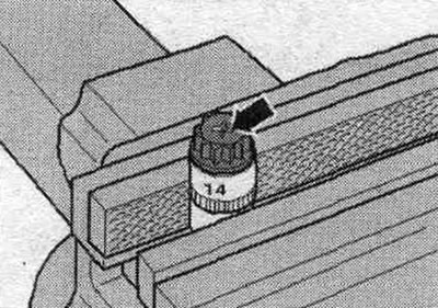
Aluminum bolts «2...11» may be used no more than 2 times. Therefore, after the first use, mark such…


Note: Bolts tightened with a tightening angle must be replaced. Replace self-locking nuts, lip seals, gaskets and seals. rings. On vehicles with the multitronic OAW transmission, a needle bearing is installed in the driven disk. Before dismantling, make sure the needle bearing is installed. Pressing in and pressing out a needle bearing from a driven disk. Hose fittings, air tubes and hoses must be cleaned of oil and grease before installation. To secure all hose connections, use clamps of the appropriate series. To ensure reliable fastening of the air duct hoses to the fittings, all cable ties should be placed in their original locations during installation.


Install the engine mounts and engine cushion. Install the right lower coolant pipe. When installing the engine on the subframe, hold the ATF lines in the mounting position. Be sure to clean the threaded holes for securing the power unit in the cylinder block with a tap before assembling the transmission. Before connecting the engine and transmission, perform the following preparatory steps. Install mont. device "T40169" from below under the gearbox housing and dual-mass flywheel, as shown in the figure. The mounting fixture should fit into the semicircular groove "1" and additionally into the inspection hole "2." To locate the inspection hole, it is necessary to rotate the dual-mass flywheel. Insert mounting bolts. devices into the hole on the gearbox housing.
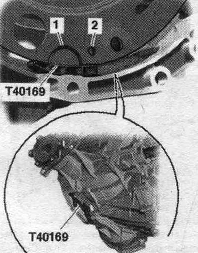
Install the engine mounts and engine cushion. Install the right lower coolant pipe. When installing…


Install the "T40170" transport protection from below under the gearbox housing and attach it to the shaft with flange "1".
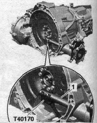
Install the «T40170» transport protection from below under the gearbox housing and attach it to the…


Check the presence of centering bushings "A" for the engine and gearbox in the cylinder block; insert the bushings if necessary. Check the aluminum engine-to-gearbox bolts for reuse and mark them if necessary. Install the gearbox onto the engine and tighten bolts 1...11. Remove transport lock "T40170" and mounting tool "T40169." This step ensures that the clutch module fits evenly on the driven disc and does not warp. Lightly press the dual mass flywheel "2" using the mounting. lever "1" to the driven clutch disc "3" "in the direction of the arrow".
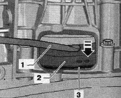


Check the presence of centering bushings «A» for the engine and gearbox in the cylinder block;…


Secure the dual mass flywheel to the driven disk as follows. To tighten the bolts use a ring spanner SW 16 "VAG 1332/14". Screw in the first "arrow" bolt by hand (2 Nm).
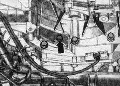
Secure the dual mass flywheel to the driven disk as follows. To tighten the bolts use a ring…


Insert the guide pins of the adapter "T40058" as shown below: the large diameter "arrow 1" faces the engine, the small diameter "arrow 2" faces the adapter.
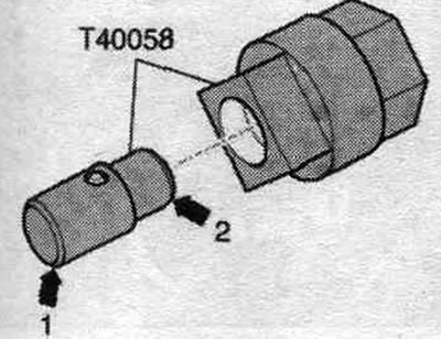
Insert the guide pins of the adapter «T40058» as shown below: the large diameter «arrow 1» faces…


Turn the crankshaft using the adapter "T40058" 180° in the direction of engine rotation "arrow". In this crankshaft position, tighten the accessible bolt to the specified torque. Turn the crankshaft 60° and tighten the remaining 5 bolts to the specified tightening torque.
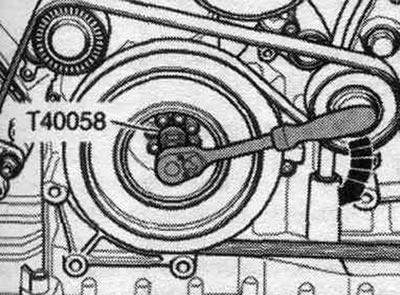


Turn the crankshaft using the adapter «T40058» 180° in the direction of engine rotation «arrow». In…


Install power steering lines. Install the tensioner element of the poly V-belt. Bolt the left and right drive shafts to the axle shafts with the transmission flanges. Install the ATF lines. Install the diesel particulate filter. Install the turbocharger heat shield. Raise the power unit using the lifting table -VAS 6131 A-. Align the subframe and tunnel crossmember in accordance with the markings made on the side members during dismantling.
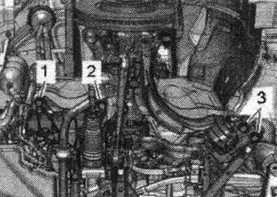
Install power steering lines. Install the tensioner element of the poly V-belt. Bolt the left and…


Tighten the subframe bolts only with a light torque, do not tighten at an angle (tighten the bolts only after checking the wheel alignment angles). Tighten the tunnel crossmember bolts. Installation in reverse order. Install the exhaust system inlet pipe. Align the system. exhaust gas release without mechanical stress. Install the front cross member. Install the selector cable. Tighten the universal joint mounting bolts to the steering gear. Install the subframe brace, upper suspension arm, stabilizer, tighten the shock absorber strut mounting bolts on the support arm. Install brake. support. Install the radiator frame crossbars. Install the engine control unit. Electrical connections and wiring. Install the wires, the 2-way splitter 30 "W22" and the cover of the motorcycle junction box. compartment.
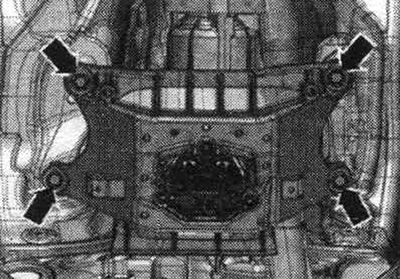


Tighten the subframe bolts only with a light torque, do not tighten at an angle (tighten the bolts…


Connect the exhaust gas temperature sensor connectors. Install the stretcher. Install the washer reservoir filler neck. Install refrigerant lines. Consider the measures taken after connecting the battery. Install the throttle module "J338", exhaust gas pressure sensor 1 "G450" and the air intake housing. filter. Fill with oil and check its level. Before starting the engine for the first time, fill the power steering expansion tank with hydraulic oil. The vane pump must not run dry. Connect the connecting pipe and coolant hose to the nipple connector. Fill with coolant.
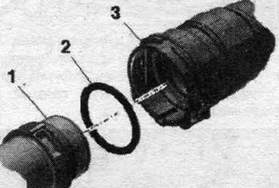
Connect the exhaust gas temperature sensor connectors. Install the stretcher. Install the washer…


Fill the air conditioning circuit. Install wheel arches. Install the front wheels and adjust the wheel alignment angles. Fill with ATF. Install noise insulation screens.
The article was checked by auto expert Timur Bazhenov
This article is available at russian, bulgarian, belarusian, ukrainian, serbian, croatian, romanian, polish, slovak, hungarian

Share information:
Previous articles
Audi A4 B8: Diesel engines 2.7/3.0 l
Next articles

Disconnecting the engine and gearbox multitronic 0AW
Engine removal for vehicles with multitronic
Technical specifications and engine number
Unit support — removal and installation
Cylinder block — poly-V drive
Cylinder block — driven disk
Cylinder block — crankshaft


Similar articles on other Audi car models:
Engine hood Audi 80 B3 (1986-1991, petrol)
Cold Engine Idle Speed Adjustment Audi 100 C3 (1982-1990, diesel)
Starting the engine from an auxiliary power source Audi A3 Type 8L (1996-2003)
Draining engine oil Audi A6 C5 (1997-2004)
Starting the engine Audi A8 D2 (1994-2002)
Engine number Audi Q5 Type 8R (2008-2017)
Towing to start the engine Audi A2 (1999-2005)
Link to this page in different formats


Visitor comments

No comments yet


How much will 17 + 21 =


A4(B8, 2007-2015) 
  • General information
  • Operating instructions
  • Power unit
  • Petrol engines 1.8 l
  • Petrol engines 1.8/2.0 l
  • Petrol engines 3.0 l
  • Petrol engines 3.2 l
  • Fuel system (petrol)
  • Diesel engines 2.0 l (CA*)
  • Diesel engines 2.0 l (CJCB)
  • Diesel engines 2.7/3.0 l
  • Diesel engines 3.0 l
  • Fuel system (diesel)
  • Transmission
  • Manual gearbox 0B1
  • Manual gearbox 0B2
  • Manual gearbox 0B3
  • Manual gearbox 0B4
  • Automatic transmission 0B5
  • Automatic transmission 0B6
  • Automatic transmission 0AW
  • All-wheel drive system
  • Chassis
  • Front suspension
  • Rear suspension
  • Brake system
  • Steering system
  • Body
  • Exterior
  • Interior
  • Seats
  • Doors, locks and windows
  • Security system
  • Heating and air conditioning
  • Electrical equipment
  • Audio system
  • Power devices
  • Equipment and devices
  • Lighting and lamps
  • Electrical circuits
 
A4(B7, 2004-2008) 
  • General information
  • Introduction to manual
  • Troubleshooting
  • Operating instructions
  • Maintenance
  • Power unit
  • Petrol engines 2.0 (ALT)
  • Petrol engines 2.0 (TFSI)
  • Petrol engines 1.8 (MPI)
  • Diesel engines
  • Cooling system
  • Air conditioner
  • Fuel and exhaust system
  • Ignition system
  • Starting and charging
  • Transmission
  • Clutch
  • Manual gearbox
  • Automatic gearbox
  • Drive shafts
  • Chassis
  • Brake system
  • Front suspension
  • Rear suspension
  • Steering
  • Body
  • Exterior
  • Interior
  • Electrical equipment
  • Equipment and devices
  • Lighting and signaling
  • Windscreen wipers and washers
  • Electrical diagrams
  • Electrical diagrams (since 2007)
 
A4(B6, 2000-2006) 
  • General information
  • Vehicle Description
  • User manual
  • Maintenance
  • Power unit
  • Gasoline engine
  • Diesel engine
  • Lubrication system
  • Cooling system
  • Supply system
  • Injection system
  • Exhaust system
  • Ignition and control
  • Transmission
  • Gear box
  • Clutch and drive shafts
  • Chassis
  • Brake system
  • Car suspension
  • Steering
  • Body
  • Heating and ventilation
  • Exterior (external elements)
  • Interior (internal elements)
  • Electrical equipment
  • Power devices
  • Lighting and appliances
  • Electrical circuits
 
A4(B6, 2000-2006, petrol) 
  • General information
  • Introduction to the guide
  • Car care
  • Power unit
  • Engine repair
  • Lubrication system
  • Cooling system
  • Injection and control system
  • Ignition system
  • Power and exhaust system
  • Transmission
  • Clutch and drive shafts
  • Car gearbox
  • Chassis
  • Suspension and wheels
  • Steering
  • Brake system
  • Body
  • Interior
  • Exterior
  • Electrical equipment
  • Equipment and devices
  • Lighting and signaling
  • Power devices
  • Electrical circuits
 
A4(B5, 1994-2001) 
  • General information
  • Introduction to the guide
  • Car care
  • Maintenance (gasoline)
  • Maintenance (diesel)
  • Power unit
  • Gasoline engines
  • Diesel engines
  • Engine overhaul
  • Cooling system
  • Fuel injection (gasoline)
  • Fuel system (diesel)
  • Exhaust system
  • Ignition system
  • Transmission
  • Clutch
  • Mechanical gearbox
  • Automatic gearbox
  • Drive shafts
  • Chassis
  • Brake system
  • Car suspension
  • Steering
  • Body
  • Exterior
  • Interior
  • Doors, locks and windows
  • Heating and ventilation
  • Electrical equipment
  • Power devices
  • Equipment and devices
  • Electrical circuits
 
A4(B5, 1994-2001, petrol) 
  • General information
  • Vehicle description
  • Maintenance
  • Power unit
  • Engine repair
  • Turbocharging
  • Exhaust system
  • Cooling system
  • Ignition system
  • Fuel system
  • Motronic injection system
  • MPI and MPFI injection system
  • Transmission
  • Clutch
  • Gearbox and shafts
  • Chassis
  • Steering
  • Car suspension
  • Brake system
  • Wheels and tires
  • Body
  • Heating and ventilation
  • Body parts
  • Electrical equipment
  • Fuses and relays
  • Power devices
  • Lighting and lamps
  • Tools and devices
  • Electrical circuits
 
AudiManual.ru © 2017-2026 · Mobile version · Feedback · Sitemap: EN BG BY UA RS HR RO PL SK HU · Site search · News and articles
80 B2 · 80 B3 petrol · 80 B3 · 80 B4 · 100 C3 diesel · 100 C3 petrol · 100 C3 · 100 C4 petrol · 100 C4 · A3 Type 8L · A4 B5 petrol · A4 B5 · A4 B6 petrol · A4 B6 · A4 B7 · A4 B8 · A6 C4 · A6 C5 · A6 C5 Allroad · A8 D2 · Q5 Type 8R · Q7 Typ 4L · Audi A2 ·
This site uses cookies 🍪. Click the button to accept this fact.