



Table of contents: Support of units ↓ Removal and installation the left… ↓ Removal and installation the right… ↓
Support of units
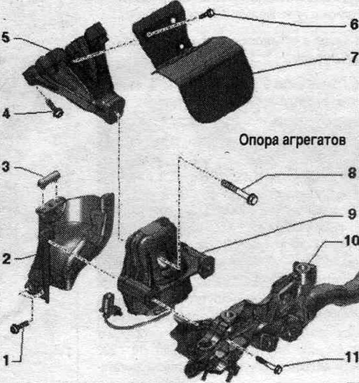
1. Bolt: 20 Nm.
2. Mounting shield: for engine mount: if the engine mount is defective, replace the mounting shield; check the mounting plate on the opposite side and replace it if necessary.
3. Bump stop: for engine mount; not supplied separately.
4. Bolt: 40 Nm.
5. Engine support.
6. Bolt: 10 Nm.
7. Thermal insulation.
8. Bolt: replace; 90 Nm + 90°.
9. Engine mount: with el. mag. electric valve. hydraulic, engine mounts; left left el. magnetic valve el. hydr., engine mounts "N144", right right el. magnetic valve el. hydraulic engine mounts "N145"; replace in pairs.
10. Subframe.
11. Bolt: 55 Nm.
Removal and installation the left engine mount
Note: To avoid repeat repairs if the engine mount is faulty, proceed as follows. Replace the defective engine mount and the corresponding mounting shield. Also replace the engine mount on the opposite side, check the corresponding mounting plate, and replace it if necessary. During installation, all cable ties should be reinstalled in their original locations.
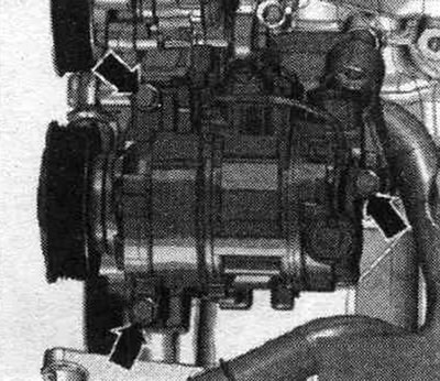
Remove the compressor. Remove the left front wheel. Remove the front left fender liner.
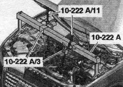
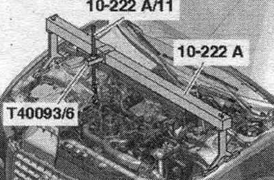
Attach the 10-222 A crossbar with the 10-222 A/3 adapters to the body next to the upper shock absorber mounts (right and left), as shown in the picture. Attach the lead screws "10-222 A/11" to the engine suspension eyes. Apply pre-tension using the lead screws.
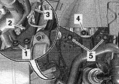
Unscrew the left bolt "2" of the subframe.
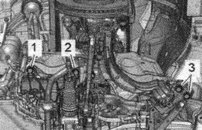
Release and disconnect the plug connector "3" of the left el. magnetic valve. hydr., engine mounts "N144". Unscrew bolts "1, 4, 5" of the left engine mount. Set aside the mounting plate "2" of the left engine mount.
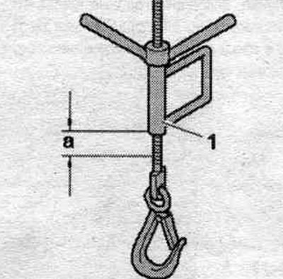
Raise the engine with the left lead screw "10-222 A/11" "pos. 1" by dimension "a". Dimension "a" = 25 mm. Remove the left engine mount.
Install
Installation in reverse order. Bolts tightened at the tightening angle should be replaced. Tighten the subframe bolts. Install the compressor. Install sound insulation and wheel arch liners. Install the front wheel.
Removal and installation the right engine mount
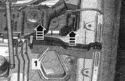
Remove the left and right elements "1" from the foam upwards in the direction of the "arrows".
Secure the 10-222 A crossmember with the T40093/6 adapters to the body next to the upper shock absorber mounts (right and left), as shown in the picture. Attach the lead screw "10-222 A/11" to the right engine mounting eye. Tighten the motor slightly on the lead screw.
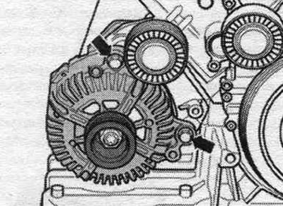
Removing the generator. Remove the front right fender liner.
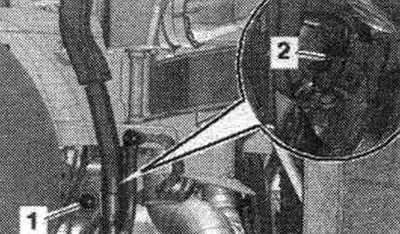
Remove the plug connector "2" of the right el. magnetic valve from the bracket. hydr., engine mounts "N145" and disconnect the connector. Unscrew nut "1" and remove the wiring harness bracket from the subframe.
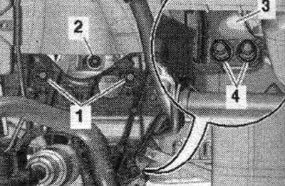
Unscrew bolts "1, 2, 4" and put aside the mounting plate "3" of the right engine mount.
Raise the engine with the lead screw "10-222 A/11" by dimension "a". Distance "a" = approx. 70 mm. Remove the right engine mount.
Install
Installation in reverse order. Install the generator. Install the front right wheel arch liner.