



Table of contents: Rear tailgate - Avant ↓ Adjusting the trunk lid ↓ Mounting position of the adjustable… ↓ Removal and installation a gas strut ↓ Removal and installation the trunk… ↓ Removal and installation the lock ↓ Removal and installation the seal ↓ Engine parts and components ↓
Rear tailgate - Avant
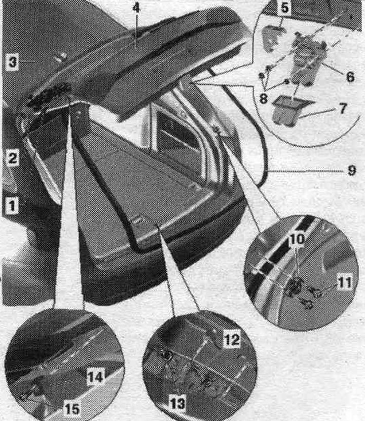
1. Gas strut: the damping element must be located on the body side.
2. Trunk hinge.
3. Electric motor in the trunk door control unit "V375".
4. Removing the trunk lid: remove the trunk trim; remove the gas struts from the lid, unscrew the hinge bolts on the left and right side of the door, open the trunk lid. Disconnect and remove the connectors and the rear washer hose. glass. On vehicles with an electric trunk lid, remove the corresponding lid drive motors.
5. Overlay.
6. Trunk lock.
7. Overlay.
8. Nut: 21 Nm.
9. Gasket.
10. Adjustable stop.
11. Bolts: 8 Nm.
12. Bracket with a finger under the lock latch: pay attention to the difference in design.
13. Nut: 21 Nm.
14. Emphasis.
15. Bolt: 8 Nm.
Adjusting the trunk lid
Gap sizes
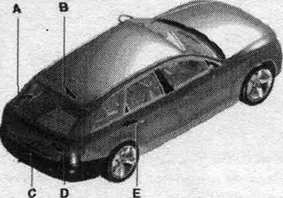
Size "A" = 3.5 mm.
Size "B" = 4.5 mm.
Size "C" = 5.0 mm.
Size "D" = 3.5 mm.
Size "E" = 2.2 mm around the perimeter.
Pay attention to the parallelism of the gaps relative to the body. Before adjusting the new rack, install gas-filled shock absorbers.
Adjustment using the lock bracket
Before adjusting, screw the adjustable buffers onto the cover completely in.
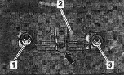
Vehicles with fixed lock bracket: Remove rear trim. trunk walls. Loosen combination nuts "1" and "3", lock bracket "2" should be able to move. Pay attention to the different designs.
Cars with door closer: Loosen the combination nuts, the lock bracket "2" with the closer motor "1" should still be able to move. To facilitate reg. there are marks on the back wall along which the lock bracket is installed.
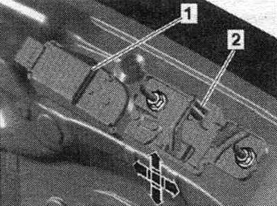
Upper and lower extreme positions of the lock bracket
For the lid adjustment, the closer motor must be in the "lid closed" position (lower extreme position). Setting the lock bracket in the upper extreme position "1" is not allowed, since in this case the lid may be damaged at the end of the closing process. When adjusting the cover, the closer motor must be disconnected from the power supply. Before adjusting the lid, screw the top of the adjustable buffer onto the lid completely.
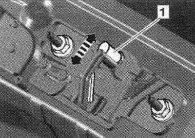
Tighten nuts "1" and "3" by hand. Close the trunk lid and check the base position. The lid lock must be latched into the main stopper (2nd fixed position). Open the cover in this position and tighten nuts "1" and "3" to torque.
Lid Lock Bracket with Soft Close: If re-installing the existing lid lock bracket, mark its position before removing. The door closer bracket may only be installed in the "lid closed" position; this position corresponds to the delivery condition of the new part. If the old lock bracket is being installed, open the lid and lock the lid lock or the rotary lever, for example, with a screwdriver. The closer will take the position "lid closed" = initial position. After this, remove the connector from the closer, and the lid lock can be opened using the handle in the lid. Lightly tighten nuts "1". Close the trunk lid and check the base position. The lid lock must be latched into the main stopper (2nd fixed position). Open the cover in this position and tighten nuts "1" to torque.
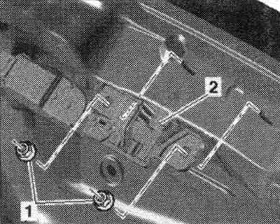
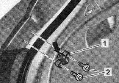
Tighten bolts "2" when mounting to the stop on the body side "1" to a torque of 8 Nm.
Unscrew the adjusting buffer "arrow" so that when the cover is closed it touches the buffers on the cover. Check that the lid closes easily and, if necessary, repeat the adjustment of the adjustable buffer. If the lid is difficult to close, tighten the adjustable buffer slightly.
Mounting position of the adjustable buffer
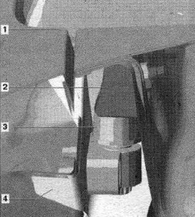
1. Trunk lid: When adjusted correctly, the adjustable buffer "3" should be in contact with the buffer "2" with slight pressure when the lid is closed.
2. Cover stop: When installing, tighten the corresponding bolts to a torque of 8 Nm.
3. Adjustable buffer on the body: the adjustable buffer is fixed to the body with screws; when installing, tighten the corresponding bolts to a torque of 8 Nm; the height adjustment is carried out using the adjusting screw, when the closed lid is adjusted correctly, the adjustable buffer should fit against the buffer on the lid with slight pressure.
4. Sidewall.
Thrust adjusting bolt
Before adjusting the lid, screw the adjusting screw "2" with the protective cap "1" fully into the buffer "3". Unscrew the adjusting screw "2" so that the protective cap "1" rests against the stop on the lid with slight pressure when the lid is closed.
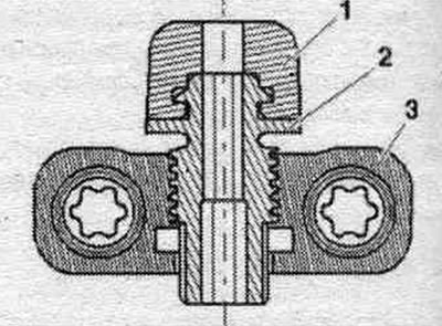
By pressing or pulling the cover by the side edges below the glass, check that there is no play in the closed cover and that its position corresponds to the template. Repeat adjustment if necessary.
Stop on the lid
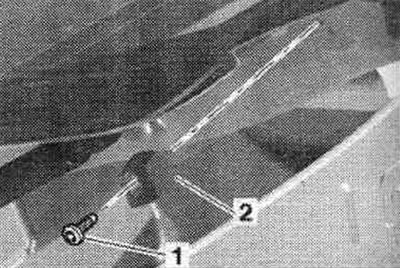
When installing stop "2," tighten screw "1" to 8 Nm. Height adjustment is accomplished using the adjustable bumper on the body.
Removal and installation a gas strut
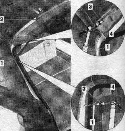
1. Gas strut: to remove, open and support the cover; lift the retaining spring "2" using a screwdriver as shown in the figure and pull the gas support "1" off the upper ball head "3".
2. Trunk lid.
3. Ball joint: 20 Nm. If the ball joint becomes loose or misaligned, it must be replaced.
4. Retaining spring: to remove the gas strut, slightly lift the retaining spring "arrow" with a small screwdriver. After completely removing the gas strut, ensure it is in the correct position during installation. The damping element must be located on the body side.
Installation
Installation in reverse order. When installing, gas struts are placed only on the ball joints.
Unlocking the retaining spring
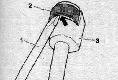
Lift spring "2" with small screwdriver "1", this will unlock gas strut "3", which can then be pulled off the ball joint.
Removal and installation the trunk hinge
On vehicles with an electric trunk drive, the lid drive units must first be removed. When installing, observe the sequence of tightening the bolts.
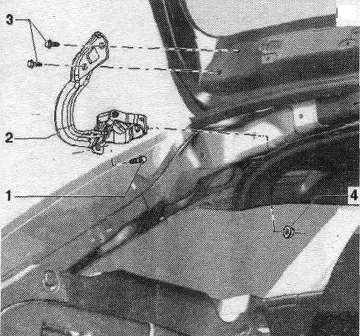
1. Bolt: 21 Nm.
2. Trunk hinge: removal: remove the curtain, remove the lid hinge cover; unscrew the bolts "3" of the cover, unscrew the bolt and hex nut "4" and remove the hinge; installation: Insert the hinge into the body and lightly secure it with nut "4" to the roof frame, then lightly secure the hinge on the side with bolt "1", secure the hinge with bolts "3", align the cover on the left and right relative to the body and secure it with bolts "3" with the proper torque, adjust the height of the cover relative to the roof and tighten bolt "1" and nut "4" with the proper torque, install the hinge cover. To avoid damage to the lid or body, support the lid and secure it from falling.
3. Bolt: 21 Nm.
4. Hexagon nut: 21 Nm.
Cover hinge cover
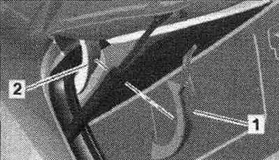
The cover is installed on the lid hinge. Release the side fasteners of cover "2" and remove it from cover hinge "1." To install, position the locking tabs opposite the holes on the hinge bracket and press the cover from the opposite side. The pad should lock into place with a distinct click.
Removal and installation the lock
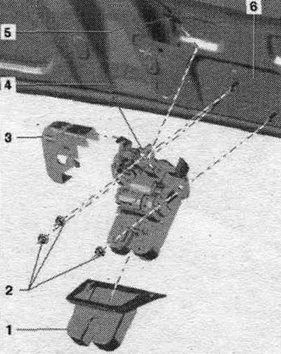
1. Cover lock trim: When installed, the trim should click into the lock; to install, place the trim on the lid lock.
2. Nut: 21 Nm.
3. Cover: place the cover on the lock with an audible locking sound.
4. Trunk lock: remove the lid lock trim, remove the trunk trim, remove the cover "3", disconnect the plug connector to the lid lock, unscrew the nuts "2" and remove the lid lock.
5. Electrical connector.
6. Trunk lid.
Removal and installation the seal
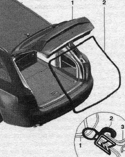
1. Tailgate seal: removal: rear panel trim. the walls are removed, secure the trunk lid from falling and remove the gas struts from the body side from the ball joints on the left and right, remove the seal along the perimeter from the body flange, align the seal during installation according to the mark on top "arrow" and press it along the perimeter into the body flange.
2. Trunk lid.
Engine parts and components
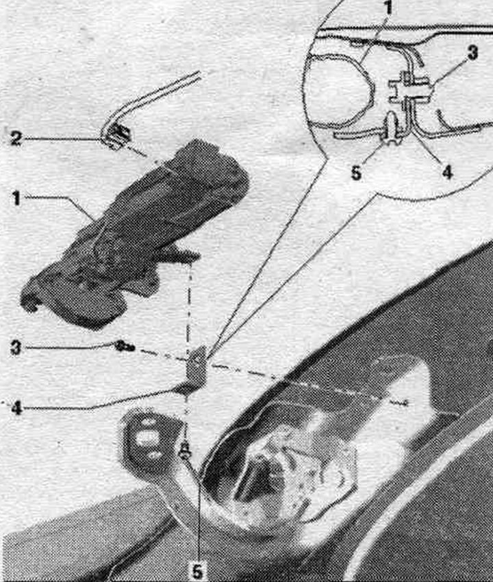
1. Motor in the trunk control unit "V375" on the left for the trunk: rear trim. roof panels removed, detach the D-pillar trim in the drive area, if necessary, carefully push to the side; disconnect plug connection "2", loosen the lock nut on the drive unit; if necessary, loosen the eccentric bolt by turning it slightly to the right, unscrew bolt "5" on holder "4", unscrew the bolt in the hinge bracket and remove the drive unit "1" in the transverse direction. The drive unit must be installed or removed only when the trunk lid is fully open. Before removing the drive unit, it is necessary to loosen the lock nut on the eccentric bolt. The eccentric bolt should have a loose fit in the hole in the hinge bracket.
2. Electrical connector: remove before dismantling the drive unit.
3. Bolt: 21 Nm.
4. Bracket: the trunk lid must be installed with gas struts, first lightly secure the holder "4" with bolt "5" on the drive unit, the holder should still remain movable, install the drive unit on the lid hinge parallel to the axis and move it until the engine bushing stops, secure the holder "4" to the body with bolt "3" and tighten with a torque of 21 Nm, tighten bolt "5" with a torque of 8 Nm. tighten the eccentric bolt with a lock nut on the drive unit with a torque. tighten the bolt on the drive fork to the specified torque. The holder is installed in a specific position at the factory using a special device, which must not be changed. When the lock nut is tightened, the eccentric bolt is fixed in the hinge. Therefore, when tightening the lock nut, it is not allowed to hold the hexagon of the eccentric bolt with a wrench. When removing the drive unit, this tightening, after loosening the lock nut, is released by briefly turning the hexagon of the eccentric bolt to the right. The drive unit bushing must fit flush with the plane of the hinge axis flange.
5. Bolt: 8 Nm.
Install the motor in the trunk control unit "V375" into the hinge
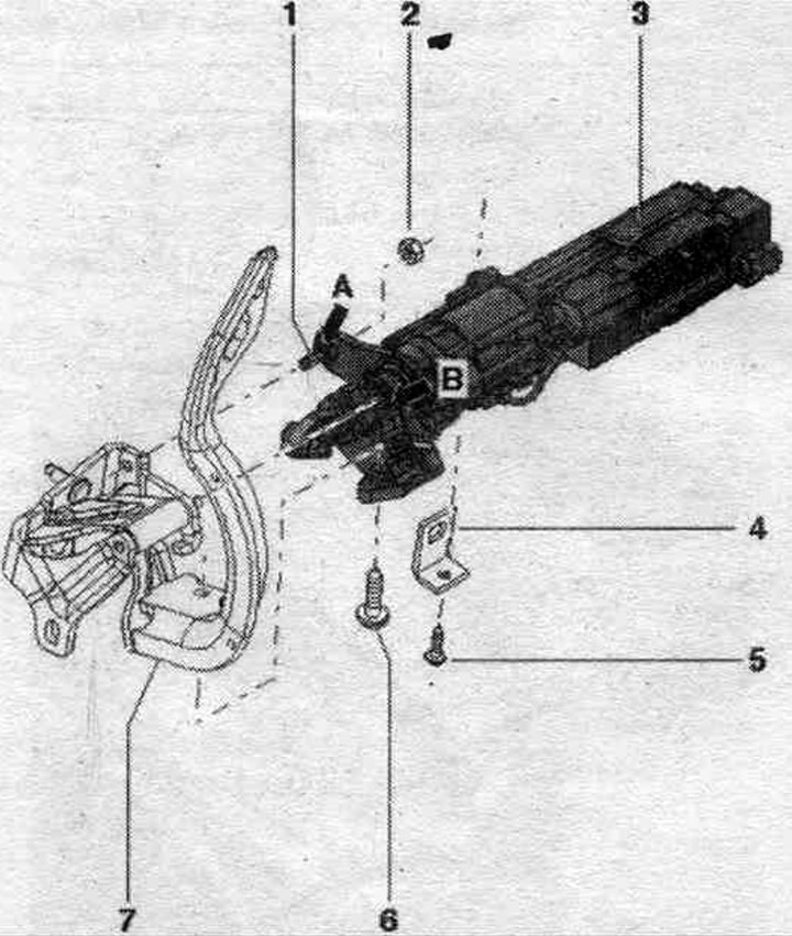
1. Hexagon eccentric bolt. When the lock nut is tightened, the eccentric bolt is fixed in the hinge. Therefore, when tightening the lock nut, it is not allowed to hold the hexagon of the eccentric bolt with a wrench. When removing the drive unit, this tightening, after loosening the lock nut, is released by briefly turning the hexagon of the eccentric bolt to the right.
2. Lock nut: Before removing the drive unit, it is necessary to loosen the lock nut on the eccentric bolt, if necessary, loosen the tightening of the eccentric bolt in the hinge bracket by turning the Allen key briefly; self-locking, 6 Nm.
3. Lid drive: insert into the hinge from the side with the sleeve "arrow B" and the loose eccentric bolt "arrow A"; in this case, the sleeve of the drive unit correctly enters the lever of the hinge "7", tighten the bolt "5" of the drive unit fastening on the holder "4" to the correct torque, tighten the lock nut "2" to the correct torque, tighten the screw "6" to the correct torque. The drive unit bushing must fit flush with the plane of the hinge axis flange.
4. Bracket. The holder is factory-installed in a specific position using a special device, which must not be changed.
5. Bolt: 8 Nm.
6. Bolt: Automatic thread rolling, 21 Nm.
7. Hood hinge.
(Read the original source on the website: Audimanual.ru)